Last updated August 19, 2026 · Reviewed by Kris Andaur, Founder & President, Southern Laboratory and Industrial
Yes, you can switch a GC from helium to hydrogen. The conversion is feasible on most instruments with proper validation, updated SOPs, and the right safety controls in place. Your first two actions: set your target linear velocity using Agilent Method Translator or Restek EZGC, then schedule a pilot validation run before committing the full lab. Southern Laboratory and Industrial (SLI) supports Gulf Coast labs through every stage of this process, from site survey through IQ/OQ, with turnkey hydrogen generator installation using LNI Swissgas and Nel Hydrogen equipment.
Table of Contents
- How do you convert a GC from helium to hydrogen step by step?
- Why linear velocity is the right conversion variable
- Which columns, detectors, and samples work well with hydrogen?
- What facility and safety requirements does hydrogen demand?
- What should you specify when procuring a hydrogen generator?
- How do you diagnose and fix common problems after switching?
- What regulatory and certification requirements apply?
- What are the environmental and waste considerations?
- What are the emergency response procedures for a hydrogen leak?
- What training do lab personnel need before handling hydrogen systems?
- Key Takeaways
- The case for a staged rollout, not a lab-wide flip
- How SLI supports your helium-to-hydrogen conversion
- Useful resources and further reading
How do you convert a GC from helium to hydrogen step by step?
Follow this ordered checklist. The full process typically runs four to six weeks for a single instrument, including validation.
- Regulatory and SOP review (Week 1): Confirm your EH&S department approves hydrogen in the lab space. Identify all affected SOPs, test methods, and instrument qualification documents that reference helium.
- Instrument compatibility check (Week 1): Verify your GC and any attached MS, detector, or sample-introduction module supports hydrogen. Flag copper plumbing, non-inert liners, and headspace or purge-and-trap accessories for remediation.
- Stakeholder sign-off (Week 1–2): Get written approval from QA, EH&S, and lab management before ordering hardware.
- Site survey and generator sizing (Week 2): Count instruments, estimate simultaneous flow demand, and confirm utilities (power, deionized water for PEM, ventilation). SLI conducts this survey as part of its turnkey service.
- Hardware and utility prep (Days 1–3 of install week): Install stainless steel tubing, inert liners, and two-stage regulators with left-hand fittings. Run conduit and DI water supply to the generator location.
- Generator installation and plumbing (Days 1–3): Mount the PEM generator, connect utilities, and perform a full leak-check at operating pressure before introducing gas to instruments.
- Method translation and pilot run (Days 4–6): Apply translated parameters (see Section 3), purge the column with hydrogen, and run a conditioning sequence before any analytical work.
- Validation and SOP sign-off (Weeks 3–4): Compare retention times, resolution, and sensitivity against your helium baseline. Update all SOPs and requalify the instrument.
Pro Tip: Start pilot runs at lower inlet temperatures and avoid reactive solvents like carbon disulfide during the first week. For GC/MS instruments, plan an overnight conditioning run to passivate the source before accepting production results.
Why linear velocity is the right conversion variable
Linear velocity (cm/s) is the absolute descriptor for carrier gas performance because it accounts for differences in gas viscosity and diffusivity between helium and hydrogen. Flow rate alone does not translate between gases; linear velocity does.
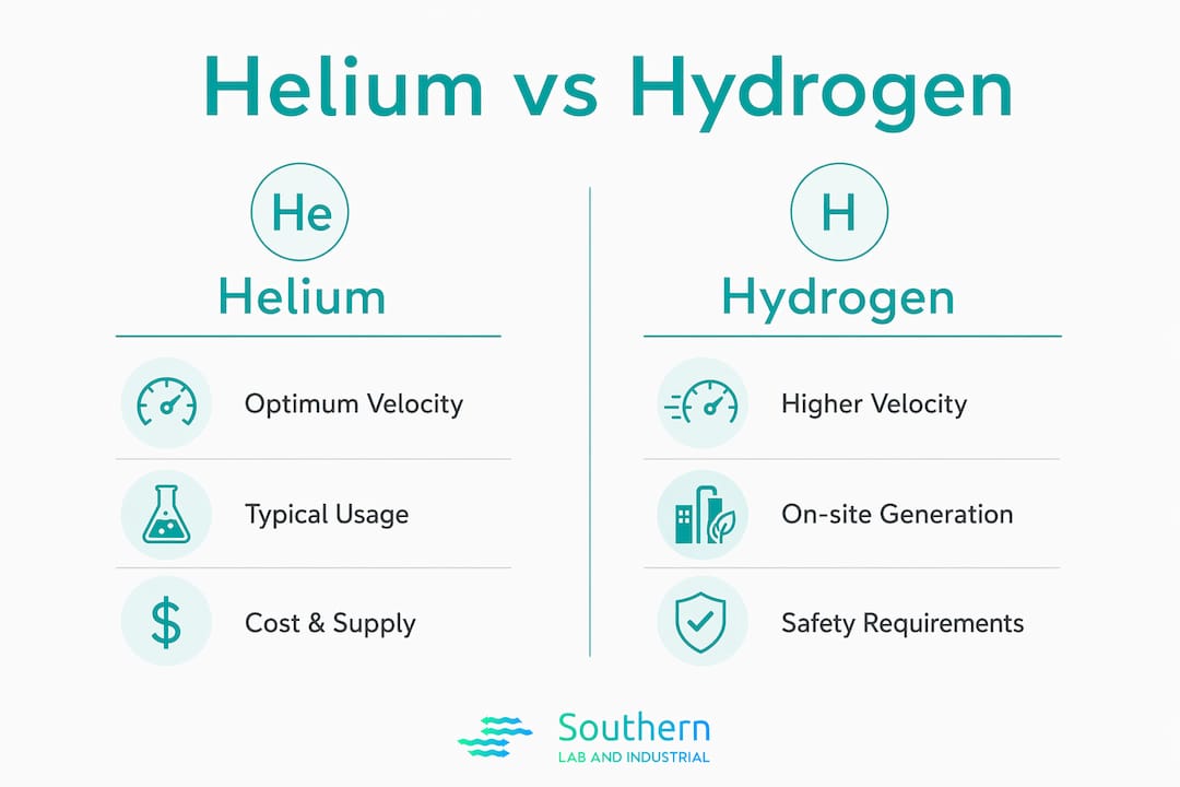
The Van Deemter curve (van Deemter, Zuiderweg & Klinkenberg, 1956) for hydrogen peaks at a higher optimum linear velocity than helium, with hydrogen allowing notably higher linear velocities than helium on a typical 0.25 mm ID column. That means you can run hydrogen faster than helium and still maintain or improve column efficiency.
| Parameter | Helium (typical) | Hydrogen (equivalent) |
|---|---|---|
| Optimum linear velocity | ~25 cm/s | ~40 cm/s |
| Column head pressure (0.25 mm) | Higher | Lower (lower viscosity) |
| Suggested column ID for GC/MS | 0.25 mm | 0.18 mm common choice |
| Method translator tool | Agilent Method Translator | Restek EZGC |
Both Agilent Method Translator and Restek EZGC compute the new head pressure, column flow, and suggested oven ramp adjustments needed to hit your target linear velocity. Run the translation, then confirm with a real chromatogram.
Validation checkpoints after translation:
- Elution order matches the helium baseline exactly
- Resolution between critical pairs meets method specification
- Inlet pressure stays above ~5 psi to maintain flow control
- Retention times fall within your method’s acceptance window
Which columns, detectors, and samples work well with hydrogen?
Most GC separations transfer cleanly to hydrogen with an inert flow path and appropriate column selection. The exceptions are specific sample-introduction techniques and a handful of reactive solvents.
Caution or incompatible items:
- Headspace and purge-and-trap systems that use carrier gas for vial pressurization or trap purging — hydrogen creates a flammable headspace inside the vial or trap
- Carbon disulfide as a solvent — it reacts with hydrogen at elevated inlet temperatures
- Copper tubing and fittings anywhere in the flow path
- Non-deactivated (active) columns and liners, which amplify hydrogen’s reactivity at hot surfaces
Mitigation checklist:
- Replace all copper plumbing with stainless steel
- Use deactivated (inert) columns and silanized liners
- Lower inlet temperatures during initial runs
- For headspace and purge-and-trap, keep nitrogen as the pressurization and purge gas while using hydrogen as the carrier
Pro Tip: A dual-gas arrangement — hydrogen as carrier, nitrogen for purge and pressurization — is the recommended approach for instruments with headspace or thermal desorption accessories. It eliminates the flammable-atmosphere risk without sacrificing the speed and cost benefits of hydrogen as the separation gas.
FID detectors run on hydrogen by design and are unaffected by the carrier-gas switch. TCD detectors require recalibration because hydrogen’s thermal conductivity differs from helium’s. GC/MS instruments need additional source preparation covered in Section 7.
What facility and safety requirements does hydrogen demand?
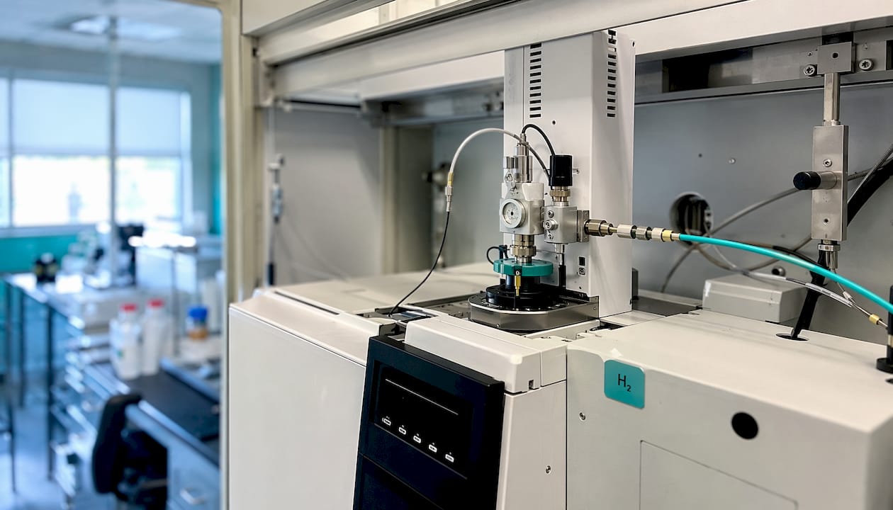
Hydrogen is safe when engineered controls are in place before the first cylinder or generator is connected. The following checklist covers the minimum requirements for a lab-scale PEM generator installation.
Facility requirements:
- Adequate ventilation: hydrogen rises and accumulates at ceiling level; confirm air exchange rate with EH&S
- Dedicated power circuit sized to the generator’s rated draw
- Deionized water supply and drain for PEM electrolysis
- Clearance around the generator for service access (typically 18–24 inches on service sides)
- No ignition sources within the immediate generator area
Safety devices and procedures:
- Fixed hydrogen detector mounted at ceiling height in both the generator room and the GC oven area, wired to an automatic shutoff interlock
- Two-stage regulators with CGA 350 left-hand fittings on all hydrogen connections
- Documented purge procedure: purge the column with hydrogen for at least 10 column volumes before applying heat
- Leak-check all fittings with an approved electronic leak detector (not a flame) at installation and after any service
- Emergency shutoff valve accessible outside the lab space
Engage EH&S and facilities at the start of Week 1. Permitting and stakeholder coordination for a lab-scale PEM generator typically runs one to two weeks, which aligns with the planning phase in the conversion checklist above.
What should you specify when procuring a hydrogen generator?
Specify continuous purity, continuous flow capacity, and surge capacity before you request a quote. A generator that meets peak demand on paper but cannot sustain it across a full eight-hour shift will create retention-time drift and pressure alarms.
Vendor specification checklist:
- Guaranteed purity: O2 and moisture content in ppm at the outlet (99.999% or better for GC/MS)
- Continuous flow rate and maximum flow in mL/min, sized to the number of instruments running simultaneously
- Purge and startup time to stable, on-spec flow
- Built-in leak detection and automatic shutoff interlocks
- Utilities required: power (voltage, amperage), DI water consumption rate, and drain requirements
- Local service SLA: response time, parts availability, and preventive maintenance schedule
Pro Tip: Size the generator to 120–130% of your calculated simultaneous instrument demand. That buffer covers method development runs, conditioning sequences, and any future instrument additions without requiring a second generator.
Acceptance tests (IQ/OQ style):
- Continuous flow verification at each instrument inlet under operating conditions
- Purity check with a calibrated oxygen/moisture analyzer at the generator outlet
- Full system leak-check at operating pressure before first analytical use
- Baseline chromatogram on each instrument compared against the helium reference
SLI’s HG Series generators from LNI Swissgas are sized and certified for GC and GC/MS applications. For labs with higher demand or industrial-scale needs, Nel Hydrogen PEM electrolyzers are available through SLI’s industrial hydrogen line. Local Houston-based service contracts cover preventive maintenance and emergency response.
How do you diagnose and fix common problems after switching?
The typical post-conversion issues are sensitivity loss in GC/MS, peak tailing, earlier elution than expected, or elevated detector noise. Each has a targeted fix.
Quick diagnostic checklist:
- Log inlet pressure and column flow immediately after switching; compare to translated method targets
- Check MS vacuum level and turbo pump load — hydrogen’s lower viscosity increases gas load on the pump
- Run a chromatogram comparison against your helium baseline and flag any peak shape or order changes
- Note any new background peaks, which often indicate outgassing from non-inert surfaces
Immediate fixes by symptom:
- Sensitivity loss (GC/MS): Condition the MS source overnight before drawing conclusions. If sensitivity does not recover, replace the extractor lens with a larger aperture (9 mm) or switch to an Agilent HydroInert source to reduce in-source reactions.
- Peak tailing: Extended overnight passivation resolves most tailing after the first hydrogen runs. Log chromatograms every two hours during conditioning to confirm stabilization before replacing hardware.
- Earlier elution than expected: Recheck linear velocity against the translated method. A higher-than-intended velocity shifts retention times earlier; reduce head pressure to hit the target.
- Elevated noise or background: Leak-check all fittings. Replace the liner and septum. Confirm the generator is delivering on-spec purity at the instrument inlet.
Recommended log fields for every troubleshooting event: timestamp, instrument ID, symptom description, inlet pressure and column flow readings, corrective action taken, and follow-up requirement. Consistent logging accelerates root-cause identification across multiple instruments. For generator-specific fault codes, SLI’s troubleshooting resource covers common post-installation issues.
What regulatory and certification requirements apply?
In the United States, hydrogen use in a laboratory falls under OSHA’s Hazardous Materials standards (29 CFR 1910.103) and NFPA 2 (Hydrogen Technologies Code). Labs operating under GLP or ISO 17025 must document the carrier-gas change in their quality system, update method validation records, and obtain sign-off from a quality manager before the new method is used for reportable results. Instrument qualification (IQ/OQ/PQ) documentation must reflect the new gas type. Confirm with your accreditation body whether a full revalidation or a change-control notification is sufficient for your specific scope.
What are the environmental and waste considerations?
Hydrogen itself produces no carbon emissions at the point of use and no hazardous waste stream. PEM electrolysis generates only hydrogen and oxygen from deionized water, making on-site generation the lowest-impact supply option compared to delivered cylinders, which carry transportation and cylinder-manufacturing footprints. The primary waste stream from a PEM generator is the periodic replacement of membrane electrode assemblies and desiccant drying columns; dispose of these per the manufacturer’s material safety data sheet. Spent DI water resin from the water purification system requires disposal as non-hazardous laboratory waste in most U.S. jurisdictions, but confirm with your local waste authority.
What are the emergency response procedures for a hydrogen leak?
Post a written emergency response procedure at the lab entrance and at the generator location. The core steps:
- Activate the nearest hydrogen detector alarm manually if automatic detection has not triggered.
- Evacuate the lab and pull the corridor fire alarm if concentrations are unknown or rising.
- Shut off the hydrogen supply at the emergency shutoff valve outside the lab space.
- Do not re-enter until EH&S or the fire department confirms the area is below the lower flammability limit (4% by volume in air).
- Identify and repair the leak source before restoring gas supply.
Fixed electrochemical hydrogen detectors set to alarm at 10–25% of the lower flammability limit give adequate warning time. Test detectors on the schedule the manufacturer specifies, typically every six months, and document each test.
What training do lab personnel need before handling hydrogen systems?
Anyone who operates, services, or works near a hydrogen generator or hydrogen-supplied instrument must complete documented training before first use. Minimum training elements:
- Hydrogen properties: flammability range, buoyancy behavior, and odorless/colorless characteristics
- Generator operating procedures: startup, shutdown, and normal alarm response
- Leak detection: how to use an electronic leak detector and how to interpret fixed-detector alarms
- Emergency response: evacuation routes, shutoff valve locations, and when to call EH&S versus the fire department
- SOP review: sign-off on all updated method and instrument SOPs before operating the converted instrument
Training records must be retained in the lab’s quality system. For labs under ISO 17025 or GLP, training competency should be assessed, not just attendance recorded.
Key Takeaways
Switching from helium to hydrogen is technically and operationally feasible for most GC and GC/MS labs, provided you anchor the conversion on linear velocity, update your quality system, and install proper safety controls before the first run.
| Point | Details |
|---|---|
| Linear velocity is the control variable | Match linear velocity (cm/s), not flow rate, to preserve retention order when converting methods. |
| Safety controls must precede gas introduction | Install fixed H2 detectors, automatic shutoffs, and left-hand fittings before connecting hydrogen. |
| Validate before production use | Run overnight conditioning and a full chromatogram comparison against your helium baseline. |
| Generator sizing needs a buffer | Size the PEM generator to 120–130% of simultaneous instrument demand to cover method development and future growth. |
| SLI provides turnkey conversion support | Southern Laboratory and Industrial (SLI) handles site surveys, generator sizing, installation, IQ/OQ, and local service contracts for Gulf Coast labs. |
The case for a staged rollout, not a lab-wide flip
The conventional advice is to convert all instruments at once to simplify gas supply logistics. That approach underestimates how differently individual instruments respond to hydrogen, particularly GC/MS systems with varying source ages, pump capacities, and column histories.
A staged rollout — one pilot instrument first, full validation before the next — gives you a real troubleshooting log before you commit the entire lab. The overnight conditioning requirement for MS sources alone means your first week of hydrogen runs will surface issues you cannot predict from a method translation spreadsheet. Running that experiment on one instrument protects the rest of your analytical capacity.
The other underappreciated point: the business case for on-site generation strengthens considerably once you account for the hidden costs of cylinder logistics. Delivery scheduling, cylinder handling, regulator changes, and the risk of running out mid-sequence all carry real labor and downtime costs that rarely appear in a simple cylinder-versus-generator price comparison. Labs that have made the switch consistently report that the operational reliability of continuous on-site supply justifies the capital investment faster than the headline payback period suggests.
How SLI supports your helium-to-hydrogen conversion
Helium supply instability is a real operational risk (USGS Mineral Commodity Summaries, February 2026), and on-site hydrogen generation eliminates it entirely. Southern Laboratory and Industrial (SLI) delivers the full conversion package for Gulf Coast labs: site survey, generator sizing, plumbing and electrical prep, PEM generator installation (LNI Swissgas HG Series or Nel Hydrogen for higher-demand applications), IQ/OQ documentation, staff training, and ongoing service contracts with local Houston-based technicians.
The difference between a smooth conversion and a three-week troubleshooting exercise usually comes down to whether the generator was sized, installed, and commissioned correctly from day one. SLI’s lab gas generator solutions cover every step, and the service contract keeps your supply continuous long after installation. Contact SLI for a site survey and generator quote tailored to your instrument count and flow requirements.
Useful resources and further reading
- Agilent: Switch to Hydrogen or Nitrogen as Alternate Carrier Gas — SOP update guidance, method translator tool access, and instrument-specific conversion notes.
- Agilent: EI GC/MS Helium to Hydrogen Conversion User Guide — Detailed column selection, inlet pressure management, and pump capacity guidance for GC/MS instruments.
- Agilent: Alternative Carrier Gas FAQ — MS source hardware changes, HydroInert source options, and conditioning protocols.
- Chromatography Online: Successfully Translating GC Methods from Helium to Hydrogen — Linear velocity theory, worked translation examples, and validation checkpoints.
- Shimadzu: Changing the Carrier Gas — Instrument-specific setup instructions, gas selector configuration, and Restek EZGC tool reference for Shimadzu GC systems.
- SLI: Hydrogen Generators for GC & GC/MS — Generator specifications, purity ratings, and flow options for single- and multi-instrument GC labs.