How automatic fault detection keeps your lab gas generator running
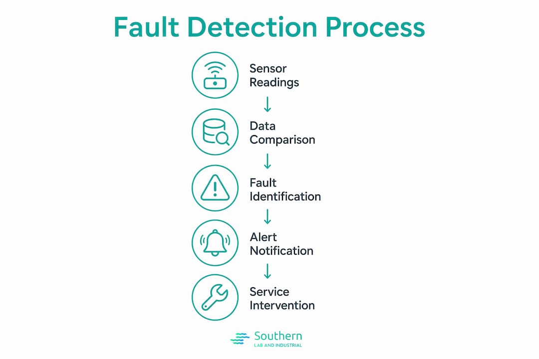
Automatic fault detection in laboratory gas generators works by continuously comparing real-time sensor readings against pre-configured operating thresholds, then triggering a warning or shutdown response the moment a reading falls outside acceptable limits. The system monitors output pressure, temperature, and gas purity simultaneously, so a developing problem rarely reaches the point of abrupt instrument failure. For lab managers running GC, ICP-MS, or LC-MS instruments, that distinction between a managed warning and an unplanned shutdown can mean the difference between a scheduled service call and a lost analytical run.
Controllers used in systems supplied by Southern Laboratory and Industrial (SLI) through partners like LNI Swissgas and Nel Hydrogen implement programmable time delays from 0 to 60 seconds before a fault lamp illuminates, filtering out transient signal spikes that would otherwise generate nuisance alarms. When a genuine fault persists beyond that delay window, the controller activates the auto-paging display and, depending on severity, lights either a yellow warning lamp or a red shutdown lamp. Relay outputs simultaneously carry the alert to remote monitoring systems or building management infrastructure.
Key mechanisms in the detection cycle:
- Threshold comparison: Sensor values for pressure, temperature, and purity are checked against preset limits on every controller scan cycle.
- Warning classification (yellow lamp): A fault condition that does not require immediate shutdown. The generator continues operating, but the condition must be corrected promptly.
- Shutdown classification (red lamp): A fault severe enough to stop the generator immediately. The unit will not restart until the controller is manually reset.
- Programmable delay timers: Two-stage timing (inhibit delay followed by fault delay) prevents false trips during startup stabilization.
- Auto-paging display: Cycles through active shutdowns and active warnings in sequence, so operators see every concurrent fault condition.
- Relay output integration: Fault status is available as a relay signal for connection to lab SCADA systems or remote notification platforms.
Table of Contents
- What types of faults do these systems detect?
- How the detection and alerting methods actually work
- What to do after a fault is detected
- Advanced diagnostic features that improve detection accuracy
- Working with SLI to keep fault detection performing at spec
- Key Takeaways
What types of faults do these systems detect?
The range of faults a lab gas generator’s automatic detection system catches is broader than most lab managers expect. Common detected faults include low output pressure from membrane degradation or a downstream leak, sensor malfunctions that produce out-of-range readings, and electrical irregularities such as voltage drops across solenoid valves. Each fault type carries a different operational consequence depending on whether the controller classifies it as a warning or a shutdown.
Faults specific to on-site lab gas generators (hydrogen via PEM electrolysis, nitrogen via PSA, zero air via compressor and filter stack) include:
- Filter saturation: A clogged molecular sieve or coalescing filter restricts flow and drops output pressure, triggering a low-pressure warning before purity degrades enough to affect GC or FTIR baselines.
- Valve connectivity loss: A solenoid valve that fails to open or close on command generates a fault code tied to that valve’s position sensor, allowing the controller to isolate the problem to a specific component.
- Supply feed irregularities: Insufficient feed water pressure in a PEM hydrogen generator or inadequate compressed air supply to a PSA nitrogen generator will register as an inlet condition fault.
- Sensor malfunctions: A failed pressure transducer or purity sensor produces a reading that falls outside its calibrated range, which the controller flags as a sensor fault rather than a process fault.
- Electrical irregularities: Voltage anomalies at the solenoid or pump motor trigger electrical fault codes distinct from process-related alarms.
Warning faults allow continued operation while signaling the need for preventative maintenance. Ignoring them consistently leads to avoidable emergency service calls. For instruments like ICP-MS that require uninterrupted carrier gas at a specified purity, a warning fault that goes unaddressed for days can escalate into a shutdown mid-sequence, corrupting a full analytical batch. SLI’s gas generation troubleshooting guidance emphasizes addressing warning conditions within the same business day they appear.
How the detection and alerting methods actually work
The detection architecture in modern lab gas generator controllers relies on cyclic self-tests rather than passive monitoring alone. The GPU-3 Gas protection unit, for example, automatically carries out a cyclical self-test at startup, checking internal circuitry health, sensor status, and process conditions before the unit enters normal operation. If any error surfaces during that self-test, the controller displays it in clear text on the LCD interface and signals it through a dedicated relay output.
During normal operation, the detection cycle continues without interruption:
- Continuous sensor polling: Pressure transducers, temperature probes, and purity sensors feed real-time data to the controller’s microprocessor on every scan.
- Clear-text fault display: Fault messages appear in plain language on the controller interface, not as cryptic numeric codes, so lab staff can read the condition directly. SLI’s error code guidance maps these messages to corrective actions.
- Color-coded lamp annunciation: Yellow for warnings, red for shutdowns. A green lamp on the control panel confirms the system senses no faults and is ready for operation.
- Event log recording: Every fault, warning, and status event is written to the controller’s event log with a timestamp, creating a retrievable history for service technicians.
- Relay output for remote alerts: Fault status signals route to relay outputs that can trigger external alarms, notify a remote monitoring system, or integrate with a lab’s building management platform.
Pro Tip: Configure the relay output on your gas generator controller to send fault alerts to your lab’s existing notification system. That way, a warning fault at 2 AM reaches the on-call technician before the morning’s GC queue starts.

What to do after a fault is detected
Responding correctly to a detected fault determines whether the event stays a minor interruption or becomes a multi-day instrument outage. The first priority after any warning fault is to read the clear-text message on the controller display and check the event log for the timestamp and any preceding status events. That sequence tells you whether the fault is isolated or part of a pattern.
Maintenance steps following fault detection, consistent with SLI and manufacturer guidance:
- Check gas inlet valves and supply pressure: Confirm the main inlet valve is fully open and that feed pressure from the source meets the generator’s specified inlet range.
- Inspect pressure regulators: Verify inlet and outlet PSI at the regulator using gauges or test ports. Adjust regulator output if it has drifted outside the manufacturer’s specified band.
- Test solenoid valve function: Check voltage across the solenoid with a multimeter. Correct voltage with no valve movement indicates a mechanical fault in the valve itself.
- Inspect electrical connections and fuses: Loose wiring or a blown fuse in the control circuit can produce fault codes that mimic process problems.
- Examine exhaust and filter integrity: For closed-loop systems, leaks in the exhaust path or a saturated filter stage will degrade performance and generate secondary fault conditions.
Data logging of fault events enables service technicians to diagnose issues from historical operational data rather than trial-and-error inspection. A recurring low-pressure warning that appears every 90 days, for instance, points directly to a filter replacement interval rather than a leak. Southern Laboratory and Industrial (SLI) technicians use logged event histories as the starting point for every service call, which shortens diagnostic time considerably.
Pro Tip: Pull the event log from your generator controller quarterly and review it with your SLI service contact. Patterns in warning frequency often predict the next maintenance need weeks before a fault escalates.
Advanced diagnostic features that improve detection accuracy
The most significant recent development in gas generator fault detection is the move from fixed-threshold logic toward adaptive algorithms that handle real-world signal variability without generating false positives. Research published in Scientific Reports describes a Self-organizing Type-3 Fuzzy Rough Wavelet Neural Network (ST3FRWNN) that achieved average fault detection rates of 99.302% and fault isolation rates of 99.324% on a high-fidelity gas system simulator, while remaining robust to 20-dB signal-to-noise conditions.
For lab gas generators, the practical benefit of adaptive logic is fewer unnecessary shutdowns. A fixed-threshold system that sees a pressure transient during a PSA cycle switchover may trip a shutdown that interrupts a running ICP-MS sequence. An adaptive system recognizes that transient as a normal cycle artifact and holds the alarm until the reading persists beyond expected bounds.
Key advances in this area:
- Adaptive fuzzy logic: Membership functions adjust to environmental noise and signal drift, reducing false positives without raising the threshold for genuine faults.
- Self-organizing neural networks: The model grows or prunes its rule base on incoming data, keeping the detection model compact and computationally efficient for real-time use.
- Neuro-fuzzy hybrid training: Combining gradient-based optimizers with Kalman filter updates produces faster convergence and more accurate fault isolation than either method alone.
- Continuous cross-validation: Rigorous validation against real acoustic-emission signals and simulator data confirms that detection accuracy holds under the noise conditions typical of industrial lab environments.
- Reduced system brittleness: Adaptive algorithms handle real-world uncertainties that cause classical threshold pipelines to generate nuisance alarms, improving detection reliability across varying operating conditions.
Southern Laboratory and Industrial (SLI) monitors developments in diagnostic technology through its integration work with LNI Swissgas and Nel Hydrogen, applying updated controller firmware and detection logic as it becomes available. Facilities managing flammable gas handling alongside on-site generation benefit directly from these advances, since tighter fault isolation reduces both false shutdowns and the risk of undetected genuine faults.
Working with SLI to keep fault detection performing at spec
Southern Laboratory and Industrial (SLI) provides turnkey installation, local technical support, and ongoing maintenance for lab gas generators from LNI Swissgas, Nel Hydrogen, and NXT Power across the Gulf Coast region. When a fault detection system flags a recurring condition, SLI technicians access the controller’s event log remotely or on-site to identify root cause before parts are ordered, cutting service time. For labs running continuous analytical workflows on GC-MS, ICP-MS, or FTIR instruments, that speed matters.
If your lab’s gas generator is displaying warning faults or you want to verify that your fault detection thresholds are correctly configured for your instruments, SLI’s team is ready to help. Explore lab gas generator solutions from Southern Laboratory and Industrial, or review common integration fault scenarios to understand where detection gaps most often appear in real lab deployments.
Key Takeaways
Automatic fault detection in lab gas generators works by comparing continuous sensor data against preset thresholds, classifying faults as warnings or shutdowns, and alerting operators through color-coded lamps, clear-text displays, event logs, and relay outputs.
| Point | Details |
|---|---|
| Two fault classifications | Yellow warning lamps allow continued operation; red shutdown lamps stop the generator and require a manual controller reset before restart. |
| Programmable delay timers | Controllers support 0–60 second delay windows to filter transient signals and prevent nuisance alarms during startup or cycle transitions. |
| Cyclic self-tests at startup | Controllers run automatic self-tests before entering normal operation, displaying any detected errors in clear text and signaling them via relay output. |
| Data logging enables predictive maintenance | Fault event histories let technicians identify recurring patterns and schedule maintenance before a warning escalates to a shutdown. |
| Adaptive algorithms reduce false positives | Advanced neuro-fuzzy detection methods achieved average fault detection rates of 99.302% in validated testing, reducing unnecessary shutdowns in variable operating conditions. |