Power protection for industrial equipment is defined as the coordinated deployment of surge protective devices, backup power systems, and workplace safety protocols to prevent equipment damage, unplanned downtime, and personnel injury from electrical disturbances. Facility managers and engineers responsible for critical operations cannot treat this as a single-product purchase. Effective power protection combines IEC 61643-11 compliant surge protective devices (SPDs), transfer switch redundancy, UPS topologies, and NFPA 70E arc flash compliance into one integrated program. Manufacturers like NXT Power, Eaton, and TrilPeak each address different layers of this problem. This guide explains how those layers work together and where most industrial facilities fall short.
What are the key types of surge protective devices for industrial power protection?
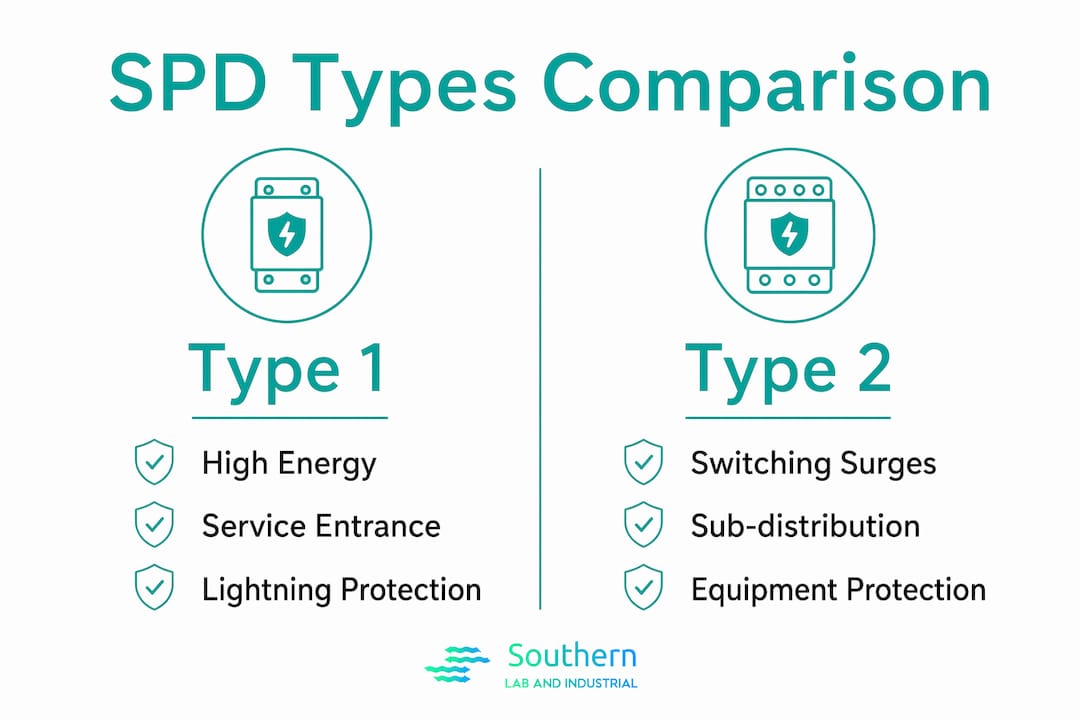
Industrial surge protection uses a coordinated cascade of Type 1, Type 2, and Type 3 SPDs per IEC 61643-11 to handle different surge waveforms at three distinct points in the electrical distribution system. Each type addresses a different threat level, and skipping any tier leaves gaps that the others cannot compensate for.
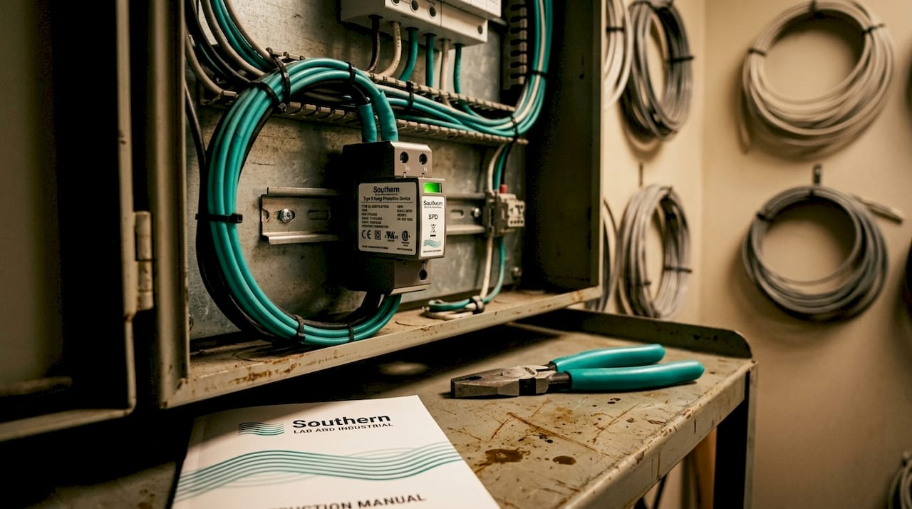
Type 1 SPDs are installed at the service entrance and are rated to handle the 10/350 µs lightning current waveform. This waveform carries significantly more energy than switching transients, which is why Type 1 devices must be rated for high impulse current. Type 1 SPDs should handle ≥50 kA lightning impulse current at the service entrance for proper protection. Under-specifying this rating shortens device service life and leaves the entire downstream system exposed during a direct or nearby lightning strike.
Type 2 SPDs are installed at sub-distribution boards and handle the 8/20 µs switching surge waveform. These devices clamp the residual energy that passes through the Type 1 device and protect branch circuits from internally generated transients caused by motor starts, variable frequency drives, and capacitor bank switching. Type 3 SPDs provide fine protection directly at point-of-use equipment, such as analytical instruments, PLCs, and control panels.
The coordination between Type 1 and Type 2 devices is a frequent source of installation errors. Mis-coordination between Type 1 and Type 2 SPDs can cause simultaneous firing, leading to SPD failure. The standard remedy is maintaining a minimum 10 meters of cable separation between the two devices. When that distance is physically impossible in retrofit or space-limited installations, Type 1+2 combined devices provide factory-coordinated two-stage protection in a single housing, eliminating the coordination distance requirement entirely.
| SPD Type | Waveform | Installation Point | Typical Use Case |
|---|---|---|---|
| Type 1 | 10/350 µs | Service entrance | Lightning current at main panel |
| Type 2 | 8/20 µs | Sub-distribution boards | Switching surges at branch level |
| Type 3 | 8/20 µs (lower energy) | Point of use | Fine protection at instruments and PLCs |
| Type 1+2 Combined | Both | Service entrance or main board | Retrofit and space-constrained installs |
Pro Tip: Never select a Type 1 SPD based on price alone. The voltage protection level (Up) rating directly determines how much residual voltage reaches your downstream equipment. For sensitive electronics, specify Up ≤ 1.5 kV even when the panel is rated for higher.
How to design redundancy and reliability into mission-critical power systems
A single transfer switch protecting a critical load is a single point of failure. Transfer switches can become critical failure points, so redundancy at the branch level and selective coordination are non-negotiable for facilities where downtime carries real financial or safety consequences.
The practical design principle is distribution of risk. Rather than routing all critical loads through one large automatic transfer switch (ATS), the preferred approach uses multiple smaller switches distributed across load groups. At least two transfer switches per branch in life-safety loads are recommended to prevent a single switch failure from causing a prolonged outage. This architecture means a failed switch takes down one branch, not the entire facility.
Effective redundancy design for industrial power systems includes the following elements:
- Multiple utility feeds from independent substations or grid sections where available, so a single utility fault does not isolate the entire facility
- On-site generation diversity, including diesel generators with different fuel storage tanks and, where feasible, natural gas or propane backup to avoid a single fuel supply dependency
- Bypass isolation switches on all critical transfer switches, allowing maintenance and testing without de-energizing the protected load
- Selective coordination of overcurrent protection, so a fault on one branch trips only the nearest upstream breaker rather than cascading to the main
- Diversified load distribution, where critical mechanical systems are spread across different transfer switches fed from different bus sections
Facility design should diversify critical loads across different transfer switches fed from different bus sections to maintain partial operation during maintenance or equipment failure. This is the difference between a planned maintenance window and an unplanned production shutdown.
Pro Tip: Schedule transfer switch exercising under load at least quarterly. A switch that has not transferred under load in 12 months may fail to close when you need it most. Document every test result and track transfer time against manufacturer specifications.
What workplace electrical safety standards are essential for industrial power protection?
NFPA 70E-2024 is the governing standard for electrical workplace safety in the United States, and it requires arc flash risk assessments before any work near energized equipment is performed. Arc flash incidents can cause severe burns at temperatures up to 35,000°F, making PPE selection a life-safety decision, not a compliance checkbox.
The arc flash risk assessment process follows a defined sequence:
- Establish the arc flash boundary by calculating incident energy at the working distance for each piece of equipment.
- Determine the PPE category based on incident energy levels. Beyond 40 cal/cm², energized work is prohibited under NFPA 70E.
- Define shock protection boundaries, including the limited approach and restricted approach boundaries for unqualified and qualified workers respectively.
- Issue an energized electrical work permit for any task that cannot be performed in a de-energized state, documenting the justification and controls in place.
- Verify insulated tool compliance with ASTM F1505 and IEC 60900 before any contact with energized conductors.
Arc-resistant switchgear changes the direction of arc flash energy but does not eliminate the need for incident energy assessment and PPE selection based on NFPA 70E. Facilities that assume arc-resistant equipment removes the PPE requirement are creating a compliance gap and a safety liability.
NFPA 70E integrates directly with OSHA’s lockout/tagout (LOTO) standard, 29 CFR 1910.147. Proper arc flash PPE is required even during lockout/tagout steps because equipment remains potentially energized until absence of voltage is confirmed with a calibrated tester. Treating LOTO as a complete safety solution before voltage verification is a procedural error that has caused fatalities.
How to select and integrate power protection systems for industrial and lab equipment
Protecting industrial and laboratory equipment requires coordinating surge protection, backup power, and system-level design decisions that account for both AC supply and DC control rails. Most facilities address the AC side adequately but overlook the DC control infrastructure entirely.
A 24 VDC industrial system requires devices with working voltage up to 26.4 V and surge voltage ratings that maintain performance across industrial temperature ranges. PLCs, distributed I/O, and process controllers all run on 24 VDC rails, and a surge event on that rail can corrupt logic, damage output cards, or trigger uncontrolled process states. Specifying DC SPDs rated for 24 V nominal with appropriate surge current capacity is as important as protecting the 480 V service entrance.
For the AC backup layer, online double-conversion UPS topologies isolate loads from utility disturbances entirely, providing voltage and frequency independence to sensitive equipment. This topology is preferred for analytical instruments, LCMS systems, ICP spectrometers, and any load where a momentary voltage sag would interrupt a measurement or corrupt a data file. Line-interactive UPS units are acceptable for less sensitive loads but should not be specified for instruments where measurement integrity depends on power quality.
Practical integration considerations that affect SPD selection and placement include:
| Factor | Impact on Selection |
|---|---|
| Panel space availability | Determines whether Type 1+2 combined or separate devices are used |
| Cable length between panels | Governs whether 10 m coordination distance is achievable |
| Instrument sensitivity (Up rating) | Sets the maximum allowable voltage protection level |
| DC rail voltage (e.g., 24 VDC) | Requires dedicated DC-rated SPDs, not AC devices |
| UPS topology | Determines whether upstream SPD coordination is needed at the UPS input |
Siemens recommends treating industrial surge protection as part of a broad reliability and maintenance program, because single SPDs do not manage all disturbance types across power and data lines. This means your SPD program should extend to data and signal lines feeding instruments, not just the power conductors. Ethernet, 4-20 mA analog loops, and RS-485 communication lines all carry surge energy into sensitive electronics if left unprotected.
Pro Tip: When specifying UPS units for laboratory instruments, confirm the output waveform is true sine wave under battery operation. Some line-interactive units switch to a stepped approximation during battery mode, which can cause instrument power supplies to fault or generate measurement noise.
Key takeaways
Effective power protection for industrial equipment requires coordinated SPDs, redundant transfer switches, compliant arc flash programs, and DC rail protection working together as a single system.
| Point | Details |
|---|---|
| Use a three-tier SPD cascade | Deploy Type 1, Type 2, and Type 3 SPDs per IEC 61643-11 at service entrance, sub-boards, and point of use. |
| Specify Type 1 SPDs at ≥50 kA | Under-rated service entrance devices fail prematurely and leave downstream equipment unprotected. |
| Distribute critical loads across multiple transfer switches | Single ATS configurations create single points of failure; branch-level redundancy limits outage scope. |
| Protect 24 VDC control rails | DC SPDs rated for industrial voltage margins are required for PLCs and distributed I/O, not just AC panels. |
| Complete arc flash assessments before energized work | NFPA 70E-2024 requires incident energy analysis and PPE selection before any work near live equipment. |
What I’ve learned from years of industrial power protection decisions
The most consistent mistake I see in industrial facilities is treating power protection as a one-time procurement decision rather than an ongoing program. A facility installs SPDs during construction, and then no one verifies whether those devices have operated and need replacement, whether the arc flash study reflects the current equipment configuration, or whether the transfer switches have been tested under load in the past two years.
The second pattern worth naming is the gap between the electrical engineer who designs the system and the facility manager who operates it. Engineers specify correct equipment on paper. Facility managers inherit systems without documentation, without test records, and sometimes without knowing what protection is installed at all. The result is that a facility may have technically adequate equipment that provides no real protection because no one is maintaining it or monitoring its status.
The third issue is under-specification driven by initial cost pressure. Choosing a Type 1 SPD rated at 25 kA instead of 50 kA to save a few hundred dollars is a decision that looks reasonable until a direct lightning strike destroys a $200,000 analytical instrument. The cost differential between adequate and inadequate SPD ratings is genuinely small compared to the replacement cost of the equipment being protected.
My recommendation is to treat the arc flash study, the SPD maintenance log, and the transfer switch test schedule as living documents that get reviewed annually. Electrical systems change. Equipment gets added. Panel configurations shift. A protection program designed for the facility as it was built in 2018 may be materially inadequate for the facility as it operates in 2026. Collaboration between the electrical engineer, the safety officer, and the facility manager is what keeps that program current.
— Kris
SLI’s power protection solutions for labs and industrial facilities
SLI specializes in power protection systems and gas generation equipment for analytical laboratories and industrial facilities along the Gulf Coast, with a focus on turnkey installation and ongoing technical support.
For facility managers evaluating critical power protection options, SLI offers NXT Power conditioning and UPS solutions designed specifically for sensitive instruments including GC, LCMS, ICP, and FTIR systems. These systems address the voltage and frequency independence requirements discussed above, with configurations suited to both laboratory benches and industrial control rooms. SLI also provides lab-grade UPS and power conditioners that integrate with existing surge protection infrastructure. Contact SLI to discuss a coordinated protection assessment for your facility.
FAQ
What is the difference between Type 1, Type 2, and Type 3 SPDs?
Type 1 SPDs handle high-energy lightning current at the service entrance using a 10/350 µs waveform. Type 2 devices manage switching surges at sub-distribution boards, and Type 3 provides fine protection directly at sensitive equipment.
When should I use a Type 1+2 combined SPD?
Use a combined Type 1+2 device when the physical cable distance between the service entrance and the first sub-board is less than 10 meters, making separate device coordination impossible without simultaneous firing risk.
What UPS topology is best for protecting analytical instruments?
Online double-conversion UPS units are the correct choice for analytical instruments because they provide continuous voltage and frequency independence, isolating the load from all utility disturbances rather than only switching to battery during severe events.
Does arc-resistant switchgear eliminate the need for PPE?
No. Arc-resistant equipment redirects arc flash energy but does not reduce incident energy at the worker’s position enough to eliminate PPE requirements. NFPA 70E-2024 still requires a full incident energy assessment and appropriate PPE selection.
How often should transfer switches be tested under load?
Transfer switches on critical circuits should be exercised under load at least quarterly, with transfer time documented and compared against manufacturer specifications to identify degradation before a real outage occurs.
Pingback: Industrial Power Conditioning Explained for Facilities – getsli.com