Even a correctly specified gas generator can cause serious instrument downtime if the installation is poorly planned. Labs running GC, LC-MS, ICP, and TOC instruments frequently report baseline noise, pressure inconsistencies, and unexpected service calls within weeks of startup, not because the hardware was wrong, but because the installation was. The wrong technology fit is one root cause, but a flawed site setup or commissioning shortcut multiplies that risk significantly. This guide walks through every critical phase: requirements alignment, site preparation, mechanical and electrical installation, and performance verification, so your lab avoids the preventable failures that erode instrument uptime and data integrity.
Table of Contents
- Understand your instrument’s gas requirements
- Plan the installation site and environment
- Step-by-step installation process
- Commissioning and acceptance: Benchmarking performance
- Why even good specs fail: The overlooked realities of lab gas generator installation
- Expert support for lab gas system installation and commissioning
- Frequently asked questions
Key Takeaways
| Point | Details |
|---|---|
| Match generator to instrument | GC and LC-MS instruments require different gas generator technologies for optimal performance and reliability. |
| Plan site environment carefully | Space, air gap, and humidity control are as crucial as generator specs to avoid costly lab downtime. |
| Follow expert installation steps | Only qualified personnel should install and commission generators, adhering to all safety and piping requirements. |
| Benchmark and verify outputs | Always validate generator purity and impurity targets using analytical acceptance testing after installation. |
Understand your instrument’s gas requirements
Before a single fitting is tightened, procurement and installation must be fully aligned with what your analytical instruments actually demand. This step is frequently underestimated, and the consequences show up weeks later as ghost peaks, elevated background noise, or mass spec sensitivity loss.
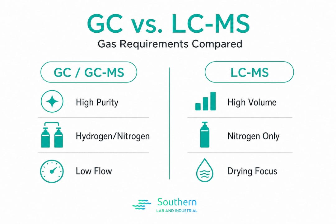
Analytical instruments fall into two broad categories when it comes to gas consumption. Purity consumers like GC and GC-MS are highly sensitive to trace hydrocarbons, moisture, and oxygen. A single part-per-million of the wrong impurity can corrupt a chromatographic run. Volume consumers like LC-MS and UHPLC interfaces depend heavily on high nitrogen flow rates to support nebulization and curtain gas functions. As the Lab Manager’s guide explains, GC requires hydrocarbon-free purity while LC-MS demands high flow rates, and a mismatched technology leads directly to background noise or operational inefficiency.
Comparison: GC vs. LC-MS gas requirements
| Parameter | GC / GC-MS | LC-MS / UHPLC |
|---|---|---|
| Primary gas | Hydrogen or nitrogen (carrier) | Nitrogen (nebulizer/curtain) |
| Purity priority | Ultra-high purity, hydrocarbon-free | High purity, high flow volume |
| Typical flow rate | 30 to 200 mL/min | 10 to 60 L/min |
| Key impurity concern | Hydrocarbons, O2, moisture | Moisture, particulates |
| Generator type match | GC/GC-MS generators | NG Series for LC-MS |
Common mismatches include using a general-purpose nitrogen generator with insufficient purity for a GC detector, or under-sizing a nitrogen generator’s output for a triple-quad LC-MS running at full source gas demand. Both scenarios produce results that look like instrument faults, which means technicians waste hours troubleshooting the instrument when the gas supply is the real problem.
Common pairing mistakes and their consequences:
- Using a single generator to feed both a GC and an LC-MS without verifying it meets both purity and flow specs simultaneously
- Selecting a hydrogen generator rated for lower-pressure demand on an instrument requiring constant 60 psi with no drop under load
- Overlooking moisture specifications when the installed generator sits near a humid air return
- Choosing a nitrogen generator based on peak flow without accounting for simultaneous multi-instrument demand
Reviewing the full range of gas generator solutions before specifying equipment helps avoid these issues before they become line items on a service invoice.
Pro Tip: Pull your instrument OEM’s service manual, not just the user guide, before selecting a generator. OEM documentation often specifies maximum allowable impurity levels that are more stringent than the standard product datasheet suggests.
Plan the installation site and environment
With your generator technology selected, a well-planned site is your next defense against performance headaches. This is especially relevant for Gulf Coast labs, where ambient humidity levels can exceed 80% for months at a time, and HVAC systems often create localized humidity pockets that directly affect generator intake air quality.

Site requirements checklist
| Requirement | Target specification | Notes |
|---|---|---|
| Floor space clearance | Min. 12 inches on all serviceable sides | Allows safe maintenance access |
| Ambient temperature | 50°F to 95°F (10°C to 35°C) | Avoid direct sunlight exposure |
| Relative humidity | 20% to 80% non-condensing | Critical for Gulf Coast labs |
| Ventilation | Free air circulation, no dead zones | Avoid closets or sealed cabinets |
| Power supply | Dedicated circuit per generator spec | Match voltage and current rating exactly |
| Floor loading | Per manufacturer’s equipment weight spec | Verify with facilities for upper floors |
As the Precision Nitrogen 250cc manual makes clear, mechanical installation details including space, ventilation, and temperature directly affect generator performance, and poor airflow can degrade gas output quality over time.
Common environmental pitfalls and their effects:
- Placing the generator directly below an HVAC return: creates humidity spikes and airborne particulate ingestion
- Installing in a corner with no side clearance: heat buildup shortens compressor and membrane life
- Routing output lines through exterior walls without proper insulation: ambient temperature swings cause pressure fluctuations
- Ignoring solvent vapor concentration near generator intakes in organic chemistry labs: some generator technologies are sensitive to VOC exposure
- Using an unregulated power circuit shared with vacuum pumps or autoclaves: voltage sags degrade generator control electronics
For labs installing LC-MS nitrogen generators or similar high-flow systems, airflow planning at the room level is not optional. A generator pushing 20 to 40 liters per minute through a pressure swing adsorption (PSA) process generates measurable heat, and that heat needs a clear path out of the installation zone.
Site planning note: Proximity to HVAC supply vents creates unpredictable air temperature and humidity at the generator intake. Even a compliant ambient temperature can mask localized condensation events that slowly damage internal components. Always map air movement across the planned installation footprint before committing to a position.
Reviewing lab gas generator applications and their corresponding environmental specs helps confirm that a given site is genuinely suitable before equipment arrives. Following lab installation safety protocols throughout this planning phase protects both personnel and equipment.
Pro Tip: Walk the installation room with a portable thermo-hygrometer at three heights (floor, bench, ceiling level) at different times of day before finalizing placement. Gulf Coast labs often have significant temperature and humidity stratification that a single-point reading misses entirely.
Step-by-step installation process
A well-prepared site ensures success. Here is how to execute the installation step by step, from unboxing through system integration.
Before you begin, assemble the following:
- Generator unit and all factory-supplied fittings, tubing, and hardware
- Leak detection solution (compatible with the gas being generated)
- Torque wrench and appropriate fittings per manufacturer specs
- Dedicated power circuit verified by a licensed electrician
- Piping or tubing per OEM specification (stainless steel or PTFE-lined recommended)
- A complete lab supply checklist to confirm no materials are missing before starting
As the ECS Wall Mount Installation and Operations Manual specifies, proper cabinet placement, dedicated power, plumbing supply lines, condensate drains, and correct system integration must all be addressed to achieve compliant installation.
Installation steps:
- Unbox and inspect: Verify all components are present and undamaged. Document any shipping damage before proceeding.
- Position the generator: Place on a level, stable surface in the pre-approved site location. Confirm clearances on all sides.
- Secure the unit: Anchor or bracket the generator per manufacturer instructions, particularly for wall-mount or rack-mount configurations.
- Connect the power supply: Use the dedicated, properly rated circuit confirmed by a licensed electrician. Verify voltage and polarity before energizing.
- Install condensate drain lines: Route drain lines to an appropriate collection point. Do not allow condensate to pool under the unit.
- Connect gas output lines: Use only the tubing type and fittings specified by the OEM. Over-tightening compression fittings is a common cause of micro-leaks.
- Connect to instrument supply ports: Follow the instrument OEM’s inlet connection specifications, including any required filtration upstream of the instrument.
- Perform a leak test before power-up: Pressurize lines and check every fitting with leak detection solution. Confirm zero leakage before proceeding.
- Power up in standby mode: Follow the OEM startup sequence; do not bypass initialization alarms.
- Verify pressure and flow at instrument: Confirm operating pressure and flow meet the instrument’s specified inlet requirements.
For specialty setups like installing TOC analyzer gas supply lines, each instrument port may require individual pressure regulation and inline filtration that must be installed before commissioning.
Safety note: Only qualified personnel should perform gas generator installation. Piping must be clean, dry, and free from burrs or particulates before connection. All lines must be properly supported to prevent stress on fittings. Any hydrogen installation requires specific attention to ventilation and leak prevention protocols due to flammability risk.
Pro Tip: Label every connection with the gas type, direction of flow, and date of installation during the install itself. This small step saves significant time during commissioning and any future troubleshooting, especially when multiple generators feed multiple instruments through shared distribution manifolds.
Commissioning and acceptance: Benchmarking performance
Once installed, rigorous verification ensures your investment performs and protects instrument integrity from day one. Commissioning is not simply switching the generator on and observing that it runs. It is a structured process of confirming that gas quality, pressure, flow, and safety systems all meet defined acceptance criteria.
Commissioning checklist:
- Initial start-up review: Confirm all installation steps are complete and documented. Verify no alarms are active.
- Full system leak test: Re-test all connections under operating pressure with the generator running. Check instrument inlet connections specifically.
- Purity and impurity verification: Measure gas purity at the instrument inlet using calibrated analytical methods. For nitrogen systems, verify key impurities against vendor targets. For example, a high-quality N2 generator should deliver CO2 below 10 ppm as a standard benchmark.
- Flow and pressure verification: Confirm that output meets instrument OEM minimum and maximum inlet specifications under actual load conditions.
- Alarm and safety system testing: Trigger each alarm condition per manufacturer procedure and verify correct response.
- Documentation and sign-off: Require formal test reports from the installing team and retain them with the instrument’s qualification records.
Setting acceptance criteria before commissioning, not after, is a discipline that protects both the instrument and the lab’s quality system. Vendor-specified impurity limits are the starting point, but your own instrument OEM specifications may impose tighter tolerances. As Parker NITROSource Plus instructions confirm, commissioning and all subsequent service must be performed by qualified personnel using only compatible, clean piping to maintain safety and long-term performance.
For instruments like ICP/ICP-MS generator commissioning, baseline noise measurements taken immediately after commissioning serve as a permanent reference point. Any future drift in instrument performance can then be evaluated against that documented baseline, separating genuine instrument issues from gas supply degradation.
The lab gas acceptance testing process should be treated as a formal quality event, not an informal walkthrough. Referencing a structured lab quality benchmark checklist during this phase ensures nothing is overlooked.
Commissioning authority: Only personnel explicitly authorized in the project scope and trained on the specific equipment model should perform start-up and acceptance tasks. This protects warranty coverage and ensures safety compliance from the first day of operation.
Pro Tip: Log every measurable parameter at first commissioning: purity, flow rate, pressure, ambient temperature, and humidity. Store this baseline in the instrument’s qualification file. When you troubleshoot issues six months later, you will have objective data instead of assumptions.
Why even good specs fail: The overlooked realities of lab gas generator installation
The technical steps matter. But there is a harder truth that experienced lab managers already sense: labs that follow spec sheets faithfully still end up with baseline noise problems, humidity-related faults, and service interruptions that were entirely avoidable. The reason is almost never the generator itself.
Most installation failures trace back to three overlooked factors. First, site microclimates that no one measured before installation day. Gulf Coast labs in particular have persistent humidity gradients that move with the weather, the season, and even the building occupancy. A generator placed in a position that was acceptable in November may be bathed in a localized humidity pocket every July afternoon. No spec sheet accounts for that.
Second, stakeholder gaps. Facilities and HVAC teams are rarely looped into gas generator projects until after installation. The result is that ventilation modifications, shared power circuit changes, or HVAC balance work happens independently of the generator’s operational needs. One lab we know of spent weeks troubleshooting unexpected purity drift before discovering that a facilities upgrade had rerouted an HVAC return directly over the generator’s intake.
Third, the checklist mindset versus the process mindset. Commissioning is treated as a box-ticking event, not an analytical baseline exercise. Smart labs treat that first commissioning run as a formal qualification event with documented acceptance criteria, witnessed sign-off, and retained records. When something changes later, they have data to compare against rather than memory.
The gas supply integration insights that distinguish reliable operations from recurring service calls are almost always procedural and organizational, not technical. Proactive monitoring, scheduled revalidation, and cross-functional communication with facilities teams are what separate labs that experience one installation and years of stable operation from those that call for service every quarter.
Expert support for lab gas system installation and commissioning
Getting the specification right is only part of the project. Installation execution, site assessment, and commissioning sign-off require hands-on expertise that is difficult to replicate from a manual alone.
SLI provides end-to-end support for labs across the Gulf Coast: from initial site evaluation and generator selection through turnkey installation and formal commissioning. Whether you are running a single GC or a multi-instrument suite with simultaneous LC-MS and ICP demand, the lab gas generator solutions available through SLI are matched to your exact purity, flow, and environmental requirements. Explore LC-MS nitrogen generators built for high-flow analytical demand, or review GC/GC-MS hydrogen generators optimized for ultra-high purity carrier gas supply. SLI’s local technical team stays with you well beyond startup, providing ongoing maintenance and revalidation support.
Frequently asked questions
Can I use the same gas generator for both GC and LC-MS instruments?
No. GC and LC-MS require different generator types because GC prioritizes ultra-high purity while LC-MS demands high-volume nitrogen flow, and a single generator optimized for one application will compromise the other.
What’s the most common installation mistake with lab gas generators?
Placing the generator near an HVAC outlet without proper clearance is the most frequent error, creating humidity fluctuations and particulate ingestion that degrade both gas purity and generator service life.
Who can legally install and commission a gas generator in my lab?
Only qualified and approved personnel should handle installation and commissioning, as required by manufacturer guidelines and laboratory safety regulations, to maintain warranty coverage and ensure compliant operation.
How do I verify that the generator meets purity and impurity requirements?
Measure gas output at the instrument inlet using your lab’s calibrated analytical methods against the targets your vendor specifies, such as CO2 below 10 ppm for high-quality nitrogen systems, and document all results in the instrument’s qualification file.
Recommended
- On-Site Lab Gas Generators & Power Protection | SLI Houston
- Laboratory Gas Generators | Hydrogen, Nitrogen & Zero Air | Southern Laboratory and Industrial
- Applications: Gas Generators & Power Protection for Lab and Industrial Instruments | SLI Houston
- Gas Supply for Incubators & Bioreactors | On-Site N₂ & H₂ | SLI Houston