A generator inlet compressor is defined as the mechanical stage that draws in, regulates, and pressurizes ambient air before it enters a gas generation or combustion system. Understanding how generator inlet compressor works is not optional knowledge for engineers and operators managing gas turbine systems, on-site nitrogen generators, or hydrogen production units. The inlet compressor sets the pressure and flow conditions that every downstream stage depends on. Get it wrong, and you face pressure instability, incomplete combustion, and accelerated component wear. Get it right, and the entire system runs at rated efficiency with predictable maintenance intervals.
How the inlet compressor regulates airflow in gas generators
Fixed speed compressors regulate output through three primary inlet valve strategies: load/unload cycling, modulation, and start/stop control. Each method addresses a different operating scenario, and selecting the wrong one for your demand profile wastes energy and shortens valve life.
Load/unload cycling is the most common approach in industrial gas generators. The inlet valve opens fully during the load phase, allowing maximum air intake. When system pressure reaches the upper setpoint, the valve closes completely, and the compressor runs unloaded. This binary operation is mechanically simple, but it creates pressure swings between the lower and upper setpoints, typically a band of 10 to 15 PSI. Those swings are acceptable in many applications but problematic in systems requiring tight pressure stability.
Modulation control uses partial valve openings to throttle incoming air continuously. Rather than switching between fully open and fully closed, the valve positions itself at intermediate angles to match actual demand. This produces a much flatter pressure curve and reduces mechanical shock on downstream components. The trade-off is higher energy consumption at part load compared to load/unload, because a partially closed valve creates pressure drop losses across the inlet.
Start/stop control shuts the motor off entirely when demand drops below a threshold and restarts it when pressure falls. This method delivers the lowest energy consumption of the three, but it is only practical for systems with low cycle frequency. Frequent starts generate heat in the motor windings and increase wear on contactors and bearings. Most manufacturers specify a maximum of six to ten starts per hour before thermal limits become a concern.
- Confirm your system’s pressure setpoints and allowable pressure band before selecting a control method.
- Evaluate cycle frequency under your actual demand profile, not peak demand.
- Check valve actuation speed against your required pressure response time.
- Verify that the control chain, including the pressure regulator and solenoid, is rated for your chosen strategy.
- Document baseline pressure curves after commissioning to detect drift early.
Pro Tip: If your system runs at partial load more than 40% of operating hours, modulation control will outperform load/unload on pressure stability, even if the energy cost is slightly higher.
IGVs vs. butterfly valves: which inlet control technology wins?
The two dominant inlet control technologies for centrifugal compressors are Inlet Guide Vanes (IGVs) and Inlet Butterfly Valves (IBVs). They both regulate airflow entering the impeller, but their operating principles and efficiency profiles are fundamentally different.
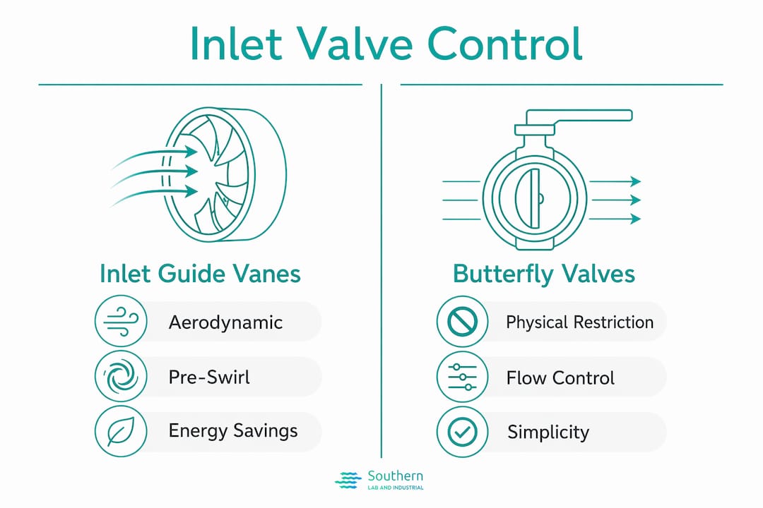
IBVs work by physically restricting the flow path. The valve disc rotates to reduce the cross-sectional area of the inlet duct, which throttles air volume and drops static pressure before the impeller. This approach is mechanically straightforward and inexpensive to install, but it wastes the energy that was used to accelerate the air before the restriction. The butterfly valve throttling method converts kinetic energy into heat rather than useful compression work.
IGVs operate on a completely different principle. Adjustable vanes at the compressor inlet rotate to impart a pre-swirl to incoming air, aligning it with the direction of impeller rotation. This aerodynamic pre-swirl reduces the relative velocity between the air and the impeller blades, which directly lowers the work the impeller must perform. IGVs reduce impeller workload by 20 to 35% at part-load conditions, a significant margin that compounds over thousands of operating hours.
The power savings are measurable and well-documented. IGV-controlled systems require approximately 63% of design power at 72% flow, compared to 72% for IBV systems. That 9-percentage-point gap translates directly to reduced operating cost in any facility running variable demand cycles.
| Feature | Inlet Guide Vanes (IGVs) | Butterfly Valves (IBVs) |
|---|---|---|
| Control method | Aerodynamic pre-swirl | Mechanical flow restriction |
| Part-load efficiency | High (63% power at 72% flow) | Moderate (72% power at 72% flow) |
| Energy waste mechanism | Minimal | Pressure drop across disc |
| Mechanical complexity | Higher (adjustable vane actuators) | Lower (single disc actuator) |
| Best application | Variable demand, centrifugal compressors | Steady-state or low-variability systems |
| Upgrade potential | Retrofit available for most industrial units | Baseline standard in older installations |
Pro Tip: If your facility operates a centrifugal compressor on a variable demand profile, upgrading from butterfly valves to IGVs is one of the highest-return mechanical upgrades available. Payback periods in industrial plants typically fall under three years.
How inlet compressors function inside gas turbine systems
The inlet compressor in a gas turbine is the first stage in the Brayton thermodynamic cycle, and its performance sets the ceiling for everything that follows. Gas turbine inlet compressors supply pressurized air to the combustion chamber, where fuel ignites at temperatures exceeding 2,000°F. Without adequate inlet pressure, combustion is incomplete, turbine output drops, and thermal efficiency falls below design specifications.

The pressure ratio delivered by the inlet compressor varies significantly by turbine class. Heavy frame turbines, which are the large baseload units common in power generation, operate at pressure ratios below 20:1. Aeroderivative turbines, derived from aircraft engine designs and used in peaking and industrial applications, exceed pressure ratios of 30:1. That higher ratio produces more work per unit of fuel but also demands tighter tolerances on inlet air temperature and cleanliness.
The mechanical link between the compressor and turbine is direct and non-negotiable. The compressor and turbine share a common shaft, with turbine torque sustaining compressor rotation throughout operation. This shared shaft arrangement means that any imbalance, bearing degradation, or alignment error in the compressor propagates immediately to turbine performance. The following points define the operational requirements that follow from this design:
- Inlet air must be filtered to prevent blade erosion and fouling on compressor stages.
- Bearing health monitoring is mandatory because shaft imbalance affects both compressor and turbine simultaneously.
- Inlet air temperature directly affects mass flow rate. Hot ambient conditions reduce air density, lowering mass flow and turbine output.
- Compressor surge, caused by flow separation on blade surfaces, can damage both the compressor and turbine stages in a single event.
- Pressure ratio stability depends on consistent inlet conditions, making inlet guide vane control critical in variable ambient environments.
For engineers working with industrial gas generation systems, understanding this compressor-turbine coupling is the foundation for diagnosing performance losses that appear to originate in the turbine but actually begin at the inlet.
Common maintenance and troubleshooting for inlet compressors
Inlet valve problems are the leading cause of pressure instability in gas generator systems, and most of them are preventable. Sticky valves caused by dust or oil contamination produce surges, excessive energy consumption, and accelerated bearing and rotor wear. The failure mode is gradual, which means operators often attribute early symptoms to demand fluctuations rather than valve degradation.
Carbon buildup and oil contamination inside the valve assembly cause partial valve openings that reduce unloading effectiveness. A valve that cannot fully close during the unload phase keeps the compressor working against backpressure, which raises discharge temperature and shortens seal life. A valve that cannot fully open during the load phase starves the system of air, causing pressure drops that trigger false alarms in downstream instrumentation.
Diagnosing inlet valve issues correctly requires examining the entire control chain, not just the valve mechanism itself. Incomplete unloading is frequently linked to solenoid vent faults or pressure regulator drift rather than a failed valve disc. Replacing the valve without checking the solenoid and regulator is the most common and most expensive diagnostic error in compressor maintenance.
Follow this diagnostic sequence when pressure instability or incomplete unloading is observed:
- Check system pressure logs for the pattern of instability. Cyclic surges suggest valve sticking; gradual drift suggests regulator calibration loss.
- Inspect the solenoid valve for vent blockage or coil failure before touching the inlet valve.
- Verify pressure regulator setpoint against the original commissioning specification.
- Remove and visually inspect the inlet valve for carbon deposits, oil film, or mechanical wear on the disc and seat.
- Test valve actuation manually with the system depressurized to confirm full travel in both directions.
- Reinstall with clean components and document the post-repair pressure curve for future comparison.
Pro Tip: Schedule systematic inlet valve inspections at intervals no longer than 2,000 operating hours. Facilities that wait for symptoms to appear before inspecting typically face repair costs three to five times higher than those running proactive maintenance programs.
Key takeaways
The inlet compressor is the single most consequential stage in any gas generation system, and its control method, valve technology, and maintenance condition determine total system efficiency.
| Point | Details |
|---|---|
| Three control strategies | Load/unload, modulation, and start/stop each suit different demand profiles and cycle frequencies. |
| IGVs outperform IBVs | IGV systems use approximately 9% less power at 72% flow by eliminating throttling losses. |
| Shared shaft dependency | In gas turbines, compressor and turbine share one shaft, so inlet problems directly reduce turbine output. |
| Control chain diagnosis | Incomplete unloading is often a solenoid or regulator fault, not a failed inlet valve disc. |
| Proactive maintenance pays | Systematic inspections at 2,000-hour intervals prevent failures that cost three to five times more to repair reactively. |
What engineers often get wrong about inlet compressors
The most persistent mistake I see in the field is treating the inlet compressor as a passive component. Engineers spend hours analyzing combustion efficiency, turbine blade condition, and fuel system performance while the inlet valve sits contaminated and partially stuck, quietly degrading everything downstream. The inlet compressor sets the conditions for the entire system. If you are chasing pressure instability and the inlet valve has not been inspected in 3,000 hours, you are diagnosing from the wrong end.
The second issue is the IGV versus IBV decision. Facilities running older centrifugal compressors with butterfly valves often accept the energy penalty as a fixed cost of operation. The data does not support that position. A 9-percentage-point power reduction at partial flow is not a marginal gain. Over a year of variable-demand operation, that difference funds the upgrade itself. The reluctance usually comes from unfamiliarity with IGV actuator systems, not from any legitimate technical barrier.
The third pattern worth calling out is single-point diagnosis. When a technician reports incomplete unloading, the reflex is to order an inlet valve. More often, the solenoid vent is blocked or the pressure regulator has drifted out of calibration. Replacing the valve without testing the full control chain wastes parts and leaves the root cause in place. Systematic diagnosis from the control signal backward to the valve mechanism is the only approach that actually resolves the problem. The gas generator flow rate relationship to inlet conditions is another area where operators frequently underestimate how much inlet valve condition affects downstream output measurements.
— Kris
SLI can support your gas generator inlet compressor needs

SLI works with engineers and facility managers across the Gulf Coast to specify, integrate, and maintain gas generation systems where inlet compressor performance is a direct factor in uptime and output quality. Whether you are evaluating a new on-site hydrogen or nitrogen generator from LNI Swissgas or Nel Hydrogen, or troubleshooting an existing system with pressure instability, SLI provides the technical support to resolve it correctly the first time. Explore real-world integration examples that show how inlet compressor configuration decisions affect system performance in actual industrial and laboratory deployments. For laboratory applications, SLI’s gas generation solutions cover the full range of on-site gas needs with local installation and ongoing maintenance support.
FAQ
What does an inlet compressor do in a gas generator?
An inlet compressor draws in ambient air, regulates its volume and pressure, and delivers it to the combustion or gas generation stage at the conditions required for stable operation. It is the first and most critical stage in the system’s thermodynamic cycle.
What is the difference between IGVs and butterfly valves?
IGVs impart aerodynamic pre-swirl to inlet air, reducing impeller load and saving approximately 9% power at 72% flow compared to butterfly valves, which throttle air by mechanical restriction and waste energy as pressure drop.
Why does my compressor fail to fully unload?
Incomplete unloading is most often caused by a blocked solenoid vent or a miscalibrated pressure regulator rather than a failed inlet valve disc. Diagnose the full control chain before replacing any components.
What pressure ratios do gas turbine inlet compressors achieve?
Heavy frame gas turbines operate at pressure ratios below 20:1, while aeroderivative turbines exceed 30:1. Higher pressure ratios increase thermal efficiency but require tighter inlet air quality and temperature control.
How often should inlet valves be inspected?
Inlet valves should be inspected at intervals no longer than 2,000 operating hours. Facilities running proactive inspection programs consistently report repair costs three to five times lower than those responding only to failures.