Gas generator integration challenges are defined as the technical, operational, and regulatory obstacles that prevent reliable generator performance when connecting to fuel systems, electrical infrastructure, control networks, or the utility grid. These obstacles appear across fuel delivery, automatic transfer switching, duty-cycle management, and interconnection queues. Facility managers and engineers dealing with examples of gas generator integration challenges will recognize four recurring failure categories: undersized fuel piping, reversed electrical polarity, incompatible control systems, and multi-year grid interconnection delays. Understanding each category with specific examples is the fastest path to avoiding costly commissioning failures and unplanned downtime in laboratory and industrial environments.
1. Common fuel system challenges in gas generator integration
Fuel pressure issues cause approximately 40% of natural gas generator startup failures. That single statistic tells you where to focus first when a new installation refuses to start or trips under load.
The most frequent gas generator integration issues in fuel delivery include:
- Undersized gas piping. A pipe sized for idle fuel draw will cause pressure droop the moment the generator ramps to full load. The generator’s fuel train interprets the pressure drop as a supply fault and shuts down. Sizing must account for peak demand, not average consumption.
- Regulator placement too close to the generator. Regulators placed near the generator face continuous heat and vibration, accelerating diaphragm wear and causing premature failure. The regulator belongs upstream, in a stable thermal environment.
- Skipping pipe pigging on new lines. Skipping pigging of new gas lines allows weld slag, pipe scale, and construction debris to migrate downstream and block regulator seats. One documented case required a complete fuel train disassembly and re-pigging after the generator failed to start during commissioning.
- Missing drip legs and sediment traps. Without drip legs at low points in the piping run, condensate and particulate accumulate and eventually reach the fuel train. This is a code requirement in most jurisdictions, not a recommendation.
- Excessive elbows and unsupported runs. Pressure losses and mechanical stress in gas piping are directly influenced by bend counts, support spacing, and the absence of flexible connectors at the generator connection point. Every unnecessary elbow adds resistance and vibration transmission.
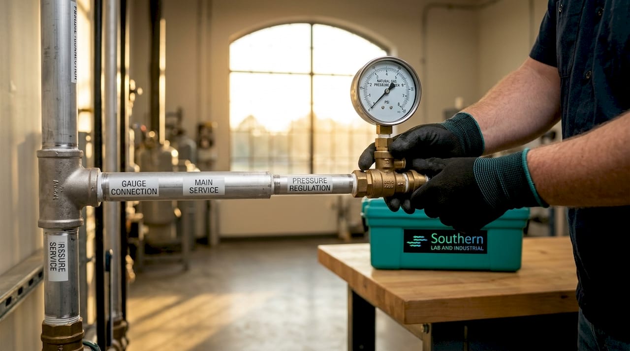
Pro Tip: Validate gas pressure not just at idle but under generator ramp and full-load conditions. Pressure regulation must be confirmed during peak fuel demand. A system that holds pressure at idle but droops under load will fail exactly when you need it most.
2. Electrical integration issues that disrupt gas generator operations
Electrical integration errors are the second most common category of gas generator deployment examples gone wrong. These failures are particularly frustrating because the generator itself operates correctly. The fault lies in how it connects to the facility’s electrical system.
The most impactful electrical obstacles in gas generator setup include:
- Reversed CT polarity. Reversed current transformer polarity causes the automatic transfer switch to misread load direction, blocking automatic transfer even when the generator is running at full capacity. This is a wiring error, not a hardware fault, but it presents as a complete ATS failure.
- Undersized ATS load cables. Undersized ATS load cables trigger protection faults and overheating under sustained load. NEC standards define minimum cable sizing for ATS installations, and deviating from those standards creates both reliability and code compliance problems.
- Floating neutral and improper neutral bonding. A generator outputting with a floating neutral can cause control board errors and automation lockouts in connected equipment. Boilers, analytical instruments, and process controllers all depend on a stable neutral reference. Improper grounding and floating neutral configurations directly trigger automation failures beyond simple safety concerns.
- Inadequate workspace and grounding per NEC. Crowded electrical panels and missing equipment grounding conductors create both inspection failures and real operational hazards during transfer events.
Pro Tip: When ATS or paralleling malfunctions arise, test CT wiring polarity before assuming the generator or ATS hardware is defective. Investigating CT polarity first saves hours of unnecessary troubleshooting.
The underlying principle here is that electrical grounding and neutral/phase configuration can directly trigger automation errors, which means electrical design must be treated as an integrated system, not a separate discipline from the generator installation itself.
3. Operational and control challenges that affect integration success
Gas generator integration solutions must address not just physical installation but also how the generator’s control system interacts with facility automation and load profiles. This is where many case studies on gas generator integration reveal hidden long-term costs.
Accelerated wear from frequent start/stop cycles. Generators designed for steady baseload operation suffer disproportionate thermal and mechanical stress when operated in frequent cycling applications. Each cold start imposes wear equivalent to hundreds of hours of steady-state operation. Facilities that add gas generators to support variable demand without adjusting the operational profile see dramatically shortened maintenance intervals.
Thermal stress and the case for modernization. Modernizing gas power plants with advanced controls reduces startup and shutdown times by over 60%, converting baseload assets into flexible resources capable of responding to fluctuating demand. Siemens Energy’s Flex-Power Services program is a documented example of this approach applied at scale.
Control system compatibility gaps. Older generator control panels often lack the communication protocols required by modern building management systems or SCADA platforms. Integrating a generator with a Modbus or BACnet network when the generator’s controller only supports hardwired I/O requires either a protocol converter or a controls upgrade. Control system and operational profile compatibility must be part of the integration scope from day one.
Warm-start and shutdown time improvements. Facilities that invest in control modernization report measurable reductions in warm-start times, which directly reduces the window of vulnerability during a power transfer event. Shorter shutdown sequences also reduce thermal cycling damage over the generator’s service life.
Operational best practices for flexible environments. Scheduling planned maintenance around load forecasts, pre-warming generators before anticipated transfer events, and logging start/stop cycles for trend analysis are all practices that extend service intervals and reduce unplanned downtime.
4. Grid interconnection challenges that delay gas generator projects
Grid interconnection is the most frequently underestimated obstacle in gas generator integration. The physical generator may be installed and commissioned on schedule while the project sits idle waiting for utility approval.
| Interconnection Path | Typical Timeline | Cost Predictability | Best Fit |
|---|---|---|---|
| Standard queue process | Nearly five years average in 2024 | Low, subject to network upgrade costs | Large capacity additions |
| Energy-only interconnection | Significantly shorter | Moderate | Facilities accepting export restrictions |
| Surplus interconnection service | Studies complete in 180 days | High, avoids most upgrade costs | Sites with existing interconnection capacity |
The standard interconnection queue averaged nearly five years from request to commercial operation in 2024, compared to under two years in 2008. That trajectory reflects the growing volume of generation projects competing for limited transmission capacity, and it has real consequences for project financing and operational planning.
Fast-track alternatives exist. Surplus interconnection service allows a new generator to use capacity already allocated to an existing interconnection agreement, completing studies in approximately 180 days and avoiding most network upgrade costs. Energy-only interconnection limits export rights but substantially reduces timeline and cost uncertainty. For facility managers integrating backup or supplemental generation, these alternatives are worth evaluating early in project planning.
The strategic recommendation is to file interconnection applications as early as possible, even before equipment procurement is finalized. Transmission study timelines do not compress regardless of how quickly the physical installation proceeds.
5. Integration challenges with sensitive laboratory and industrial equipment
Connecting gas generators to analytical instruments, process controllers, and laboratory equipment introduces a set of obstacles that differ from standard commercial generator integration. The equipment tolerance for voltage deviation, waveform distortion, and neutral configuration is far tighter.
- Voltage stability and sine wave quality. Sensitive electronics including gas chromatographs, ICP-MS systems, and FTIR spectrometers require stable voltage and low total harmonic distortion. A generator without an automatic voltage regulator capable of tight regulation under step loads will cause instrument faults or data corruption.
- Phase and neutral configuration. Boilers and process controllers may fail automation if the generator’s neutral/phase behavior does not match the equipment’s expected configuration. This is particularly relevant when generators run in parallel with utility power or other on-site generation.
- Transfer switch configuration errors. Manual transfer switches reduce cost but require human intervention during a power event. ATS systems eliminate that dependency but must be configured correctly for the load type. Mismatched ATS configurations are a documented source of instrument damage and process interruption in laboratory environments.
- Generator sizing for lab loads. Laboratory loads are often non-linear and include significant inrush current from centrifuges, vacuum pumps, and refrigeration compressors. Undersizing the generator for these transient loads causes voltage sag that trips sensitive instruments even when the generator is running normally.
For engineers managing gas generator flow rates and pressure delivery to analytical instruments, the same discipline applied to fuel system design applies to electrical integration. Both require validation under actual operating conditions, not just nominal specifications.
Key takeaways
Successful gas generator integration requires validated fuel delivery, correct electrical polarity and grounding, control system compatibility, and early interconnection filing. Skipping any one of these disciplines creates failures that are expensive to diagnose and correct after commissioning.
| Point | Details |
|---|---|
| Fuel system validation | Confirm gas pressure under full-load conditions, not just idle, before signing off on commissioning. |
| CT polarity testing | Test current transformer wiring polarity before assuming ATS or generator hardware faults. |
| Control compatibility | Include control system protocol compatibility in integration scope from the project start. |
| Interconnection timing | File grid interconnection applications as early as possible to avoid multi-year queue delays. |
| Lab equipment grounding | Validate neutral bonding and grounding configuration before connecting sensitive analytical instruments. |
What field experience actually teaches about integration failures
I have seen more gas generator integration failures traced back to skipped commissioning steps than to defective equipment. The fuel line that was never pigged, the CT wires that were never polarity-tested, the ATS that was sized for the panel nameplate rather than the actual connected load. These are not exotic failure modes. They are the predictable result of treating commissioning as a formality rather than a verification process.
The most instructive case studies on gas generator integration share a common thread: the failure was detectable before it became a failure. Gas-side pressure behavior under load is the best early signal for fuel system problems. CT polarity can be confirmed with a clamp meter before the first transfer test. Neutral bonding can be verified with a multimeter before any sensitive equipment is connected.
What I have found consistently is that integration failures multiply when gas, electrical, and controls teams work in sequence rather than in parallel. The fuel system team finishes, the electrical team starts, and the controls team arrives last. By that point, the decisions that affect control system compatibility have already been made. Bringing all three disciplines into the design review before procurement avoids the most expensive rework.
For facility managers on the Gulf Coast integrating generators with laboratory instruments, the additional complexity of sensitive load requirements makes this coordination even more critical. A generator that performs acceptably on a commercial load may still cause instrument faults on an ICP-MS or GC system if voltage regulation and grounding are not specifically addressed.
— Kris
How SLI supports gas generator integration for labs and industry

SLI specializes in on-site gas generation and power protection systems for analytical laboratories and industrial facilities along the Gulf Coast. If your facility is working through the obstacles described in this article, SLI’s technical team provides turnkey support covering fuel system design, electrical integration review, and commissioning validation. SLI partners with LNI Swissgas, Nel Hydrogen, and NXT Power to deliver certified equipment matched to the specific demands of instruments like GC, ICP-MS, LCMS, and FTIR. Explore SLI’s full range of laboratory gas generators or contact the team directly to discuss your integration requirements and get a system configured for your application.
FAQ
What causes most gas generator startup failures?
Fuel pressure problems cause about 40% of natural gas generator startup failures, most often from undersized piping, poor regulator placement, or debris in unpigged fuel lines.
How do you fix a gas generator ATS that won’t transfer automatically?
Check current transformer polarity first. Reversed CT polarity is a frequent cause of failed automatic transfers even when the generator is running correctly.
How long does grid interconnection take for a gas generator project?
The standard interconnection queue averaged nearly five years from request to commercial operation in 2024. Surplus interconnection service can reduce that to approximately 180 days for qualifying sites.
Why do sensitive lab instruments fault when running on generator power?
Floating neutral configurations and poor voltage regulation are the primary causes. Improper grounding and floating neutral configurations trigger control board errors and automation lockouts in instruments that depend on a stable neutral reference.
What is the most overlooked step in gas generator commissioning?
Validating gas pressure under full-load conditions is consistently skipped. Pressure regulation must be confirmed during peak fuel demand, not just at idle, to verify the system will perform when it matters.
Pingback: How Gas Generator Startup Sequence Works: A Technical Guide – getsli.com
Pingback: Gas Generator Cycle Time: What Industrial Pros Need to Know – getsli.com
Pingback: Why Generators Need Local Technical Support – getsli.com
Pingback: Gas Generator Supplier Qualification Steps for 2026 – getsli.com
Pingback: Gas Generation Regulatory Compliance Procurement Guide – getsli.com