Gas generator cycle time is defined as the total duration required for a gas generator system to complete one full operational cycle, from initiation through steady-state operation to shutdown. Understanding this parameter is not optional for engineers managing gas supply systems in analytical laboratories or industrial facilities. It directly governs throughput, system stress, and the reliability of downstream instruments like GC, ICP-MS, and FTIR analyzers. Whether you are working with on-site nitrogen generators from LNI Swissgas or hydrogen systems from Nel Hydrogen, cycle time shapes every performance metric you track.
What is gas generator cycle time and how long does it typically last?
Gas generator cycle time refers to the measured duration of one complete operational sequence in a gas generator system. The term covers two distinct contexts that professionals often conflate: rocket propulsion systems and industrial or laboratory gas generators. Recognizing the difference is the first step toward applying cycle time data correctly.
In rocket propulsion, the gas generator cycle is classified as an open-cycle, pump-fed propulsion method where a small portion of propellant combusts in a separate gas generator to drive turbopumps, with exhaust gases vented overboard. Validated test durations for rocket gas generator systems include a 635-second flight-duration test and an 800-second endurance hot-fire test, with cumulative operation reaching 1,900 seconds across multiple campaigns. These figures represent discrete, timed cycles with defined start and stop points.
Industrial gas turbines operating in simple-cycle mode follow a fundamentally different pattern. Industrial gas turbines run a continuous thermodynamic cycle through four stages: intake, compression, combustion, and exhaust. There is no discrete “cycle time” measured in seconds the way rocket engineers track it. Instead, cycle performance is evaluated through steady-state efficiency, which reaches 20% to 35% in simple-cycle mode and climbs to 60% to 80% in combined-cycle configurations with waste heat recovery. That efficiency gap is significant. It means the choice between simple and combined cycle operation is not just an engineering preference but a cost decision with measurable impact on operating budgets.
For laboratory gas generators supplying hydrogen, nitrogen, or zero air, cycle time typically refers to the startup-to-steady-state interval and the scheduled regeneration or purge cycle duration. These cycles are measured in minutes rather than seconds or hours, and they directly affect instrument uptime.
| System type | Cycle time range | Cycle nature | Efficiency range |
|---|---|---|---|
| Rocket engine gas generator | 635 to 1,900+ seconds (cumulative) | Discrete, timed | Propulsion-specific |
| Industrial simple-cycle gas turbine | Continuous operation | Steady-state thermodynamic | 20% to 35% |
| Industrial combined-cycle turbine | Continuous operation | Steady-state with heat recovery | 60% to 80% |
| Laboratory on-site gas generator | Minutes (startup + purge cycles) | Scheduled intervals | Purity and flow dependent |
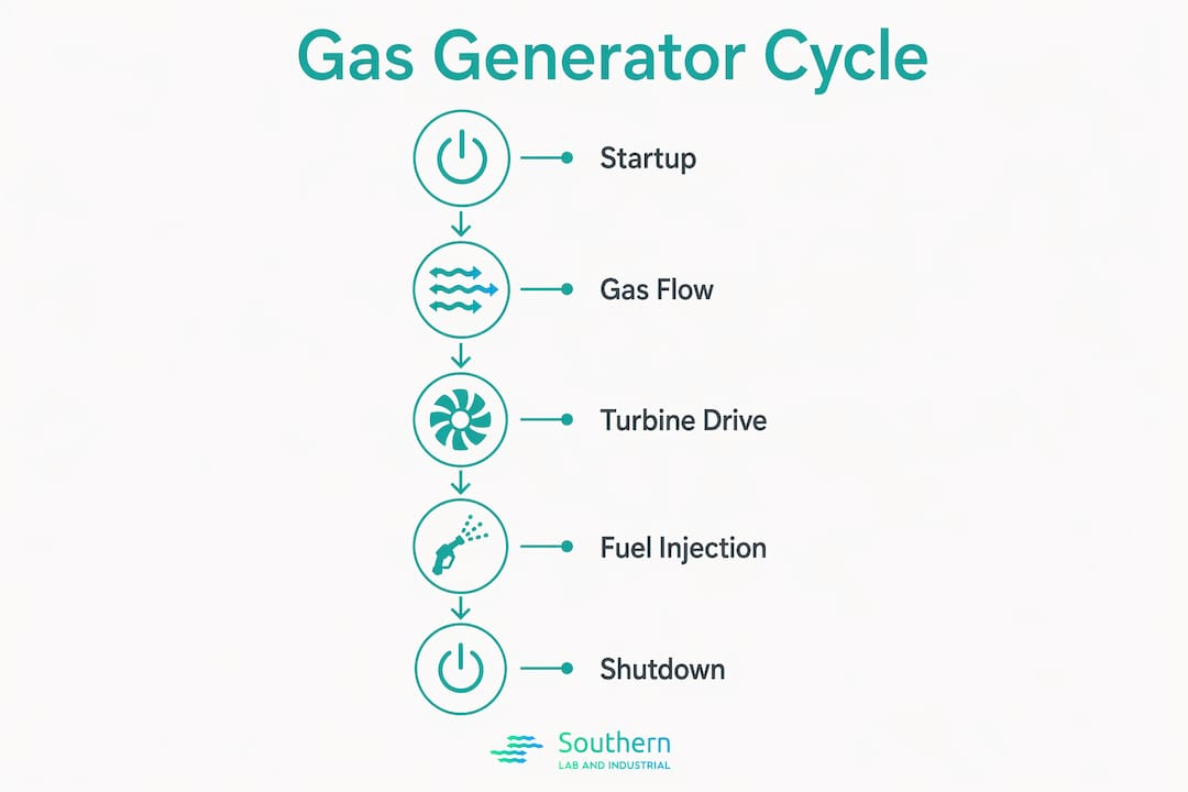
How does one complete gas generator cycle work step by step?
Understanding the sequence inside a single cycle clarifies why timing precision matters so much. The following steps describe a complete cycle for a liquid-propellant rocket gas generator, which provides the clearest discrete example. Industrial and laboratory systems follow analogous logic at different timescales.
- Propellant valve opening. Fuel and oxidizer valves open in a controlled sequence. The timing of this step, measured in milliseconds, determines whether the combustion chamber receives the correct mixture ratio from the first instant of ignition.
- Ignition. A pyrotechnic or spark igniter initiates combustion in the gas generator chamber. The start-up process involves rapid changes in mass flow, temperature, pressure, and rotational speed within seconds, demanding precise timing to avoid unstable transitions.
- Turbopump spin-up. Hot combustion gases drive the turbine, accelerating the turbopump from rest to operating speed. This transient phase is the most mechanically stressful portion of the cycle. Improper simulation of this start-up path leads directly to instability, which is why rigorous start-up threshold determination is treated as a non-negotiable design requirement.
- Steady-state operation. The turbopump reaches design speed and delivers propellant at the required flow rate and pressure to the main thrust chamber. This phase constitutes the majority of total cycle duration.
- Throttle or load adjustment. In both rocket and industrial systems, load changes alter combustion temperature and pressure, requiring control system responses measured in fractions of a second.
- Shutdown sequence. Propellant or fuel valves close in a defined order to prevent hard shutdowns that cause thermal shock. The shutdown sequence timing is as critical as startup for component longevity.
- Post-cycle purge. Residual gases are purged from the system. In laboratory generators, this step resets the system for the next demand cycle and protects membrane or electrolysis components from contamination.
For laboratory hydrogen and nitrogen generators, steps 1 through 3 compress into a startup interval typically lasting 5 to 30 minutes depending on system size and design. The steady-state phase then runs continuously until a scheduled maintenance purge or a demand-triggered regeneration cycle interrupts it.
What factors affect optimal gas generator cycle time?
Several variables determine whether a gas generator completes its cycle within the design window or deviates in ways that reduce efficiency and increase wear. Professionals optimizing gas supply systems need to track each of these factors independently.
- Fuel and oxidizer mixture ratio. Off-ratio combustion changes flame temperature and gas enthalpy, directly altering the energy available to drive turbines or sustain steady-state output. Even small deviations from the design ratio extend or compress cycle phases unpredictably.
- Thermodynamic operating conditions. Inlet pressure and temperature set the baseline for every downstream stage. Higher inlet temperatures reduce compression work but also increase thermal stress on turbine blades and heat exchanger surfaces.
- Turbopump and turbine design characteristics. Rotor inertia determines how quickly a turbopump accelerates during startup. High-inertia designs extend the spin-up phase and increase the total cycle time before steady-state is reached.
- Control system timing and precision. Valve actuation delays, sensor response times, and feedback loop latency all accumulate during transient phases. A control system that responds 50 milliseconds late during startup can shift the entire cycle timeline by several seconds in rocket applications.
- Material and thermal management constraints. Components with lower thermal conductivity require longer warm-up periods before reaching operating temperature. Additive manufacturing techniques such as laser powder bed fusion and direct metal laser sintering now enable complex internal cooling geometries that reduce warm-up time and improve thermomechanical durability across repeated cycles.
- Ambient and facility conditions. For laboratory generators, room temperature, supply water quality for electrolysis systems, and feed gas pressure all shift the startup interval and regeneration cycle duration.
- Maintenance state of consumables. Worn desiccant beds, degraded membranes, or fouled catalysts extend purge and regeneration cycles, adding minutes to what should be a predictable interval.
Pro Tip: Log cycle start and end timestamps automatically using your generator’s data output port. Comparing cycle duration trends over 30-day intervals reveals degradation in desiccant beds or membrane performance weeks before a fault alarm triggers, giving you time to schedule maintenance without an unplanned shutdown.
The design flexibility of gas generator cycles, particularly the ability to develop sub-systems independently, reduces technical risk during optimization. When you isolate the gas generator from the main process loop for testing, you can characterize cycle time behavior without disrupting production or analytical instrument schedules.
How does the gas generator cycle compare to other power cycles?
The gas generator cycle is not the only architecture available for pump-fed propulsion or industrial power generation. Staged combustion and expander cycles offer different trade-offs that affect both cycle time and system complexity.
| Cycle type | Cycle time complexity | Efficiency | System complexity | Primary application |
|---|---|---|---|---|
| Gas generator (open cycle) | Short startup, simple transients | Lower (propellant loss) | Low to moderate | Workhorse rocket engines, industrial turbines |
| Staged combustion (closed cycle) | Longer startup, complex transients | Higher (no exhaust loss) | High | High-performance rocket engines |
| Expander cycle | Moderate startup | Moderate to high | Moderate | Upper-stage engines, cryogenic systems |
| Combined-cycle industrial | Continuous, no discrete cycle | 60% to 80% | High | Utility power generation |
The open-cycle gas generator discards turbine exhaust overboard, which limits overall efficiency but keeps the startup sequence shorter and the transient behavior more predictable. Staged combustion cycles route all propellant through the turbine before combustion, recovering the energy that the gas generator cycle loses. The trade-off is a significantly more complex startup sequence with tighter timing tolerances. For laboratory and industrial gas supply applications, this distinction translates directly into a preference for simpler generator architectures where predictable cycle times matter more than peak thermodynamic efficiency.
Advanced modeling tools including computational fluid dynamics and finite element analysis now allow engineers to simulate cycle time behavior across a range of operating conditions before committing to hardware. This capability reduces development time and lowers the cost of optimizing cycle parameters for a specific facility or instrument load profile.
Key takeaways
Gas generator cycle time is the single most operationally significant timing parameter in any gas generation system, and managing it precisely separates reliable facilities from ones that experience chronic instrument downtime.
| Point | Details |
|---|---|
| Cycle time definition | The total duration of one complete operational sequence, from startup through steady-state to shutdown. |
| Context matters | Rocket systems measure discrete cycles in hundreds of seconds; laboratory generators measure startup and purge intervals in minutes. |
| Startup timing is critical | Improper start-up sequencing causes instability; precise threshold control is required for safe, repeatable cycles. |
| Key influencing factors | Mixture ratio, thermodynamic conditions, control system latency, and consumable condition all shift cycle duration. |
| Manufacturing advances | Additive manufacturing enables better cooling geometries, reducing warm-up time and extending component life across repeated cycles. |
Why cycle time precision is the metric most facilities undervalue
From my experience working with laboratory and industrial gas supply systems, cycle time is consistently the last parameter facilities decide to track formally, and it is almost always the first one that explains a recurring problem. Engineers focus on purity, pressure, and flow rate because those numbers appear on instrument specifications. Cycle time does not appear on a spec sheet, so it gets treated as a background variable.
That assumption costs facilities real money. A nitrogen generator whose regeneration cycle has drifted from 12 minutes to 19 minutes over six months is telling you something specific about desiccant condition or feed air quality. If you are not logging cycle duration, you are reading that signal as random instrument noise instead of a maintenance indicator with a clear corrective action.
The aerospace research on start-up dynamic characteristics makes a point that applies equally well to laboratory systems: unstable transitions during startup are not random failures. They are the predictable result of imprecise timing control. The same logic holds for a hydrogen generator supplying a GC system. If the startup interval varies by more than 10% between cycles, something in the control sequence or consumable stack is degrading.
My practical advice is to treat cycle time as a leading indicator rather than a lagging one. Purity alarms and pressure faults are lagging indicators. They tell you a problem has already affected your output. Cycle time drift tells you a problem is developing, and you still have time to act. Modern generators from LNI Swissgas and Nel Hydrogen provide data outputs that make this kind of trending straightforward. Use them.
— Kris
How SLI helps you control and optimize your gas generator cycles
SLI works directly with industrial facilities and analytical laboratories along the Gulf Coast to specify, install, and maintain gas generation systems where cycle time reliability is not negotiable. Whether your facility runs hydrogen generators for GC-MS applications or nitrogen systems for ICP instruments, SLI’s technical team brings hands-on experience with the integration challenges that affect cycle performance in real operating environments.

SLI partners with LNI Swissgas and Nel Hydrogen to supply systems with transparent data outputs, so your team can track cycle duration trends and act before consumable degradation affects instrument uptime. If you are evaluating on-site generation for your laboratory or production floor, SLI’s lab gas generation solutions cover hydrogen, nitrogen, and zero air with turnkey installation and local support. Reach out to SLI to discuss cycle time requirements specific to your instrument load and facility conditions.
FAQ
What is the standard definition of gas generator cycle time?
Gas generator cycle time is the total duration of one complete operational sequence in a gas generator system, covering startup, steady-state operation, and shutdown or purge. The specific duration varies by application, from hundreds of seconds in rocket propulsion to minutes in laboratory on-site generators.
How long does a typical gas generator cycle last in industrial settings?
Industrial gas turbines in simple-cycle mode operate continuously without discrete timed cycles, while laboratory on-site generators complete startup-to-steady-state intervals in roughly 5 to 30 minutes depending on system size and design. Regeneration or purge cycles add additional scheduled intervals that vary by generator type.
What causes gas generator cycle time to increase over time?
Cycle time drift is most commonly caused by degraded consumables such as desiccant beds or membranes, changes in feed gas pressure or quality, and control system latency accumulating from sensor wear. Tracking cycle duration over 30-day intervals identifies these causes before they trigger a fault condition.
Why is startup timing so critical in gas generator cycles?
The startup sequence involves rapid simultaneous changes in mass flow, temperature, pressure, and speed, and imprecise timing during this phase causes unstable transitions that can damage components or produce off-spec gas output. Precise threshold control during startup is the single most important factor in achieving repeatable, stable cycle operation.
How does the gas generator cycle differ from a staged combustion cycle?
The gas generator cycle is an open cycle that vents turbine exhaust overboard, producing shorter and simpler startup transients at the cost of some efficiency. Staged combustion cycles recover that exhaust energy but require significantly more complex timing control during startup, making them less practical for applications where cycle simplicity and predictability are the priority.