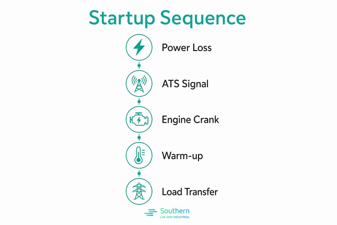
The gas generator startup sequence is defined as the automated, controller-managed process that initiates engine cranking, regulates warm-up, and transfers electrical load from utility power to the generator following a detected power failure. Understanding how this sequence operates is not optional for operators and technicians. It determines whether your standby system responds safely, avoids backfeed hazards, and meets compliance requirements. Manufacturers like Generac and KOHLER have codified this process into precise controller logic, and knowing each stage gives you the diagnostic foundation to commission, troubleshoot, and maintain these systems with confidence.
How gas generator startup sequence works: power loss detection and initiation
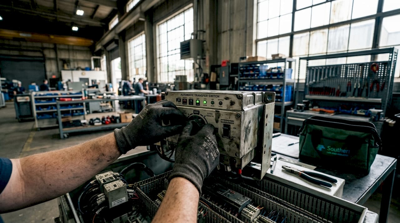
The automatic transfer switch (ATS) is the first component to act when utility power fails. It monitors incoming line voltage continuously, and the startup process does not begin until that voltage drops below a defined threshold. For common standby systems, the controller initiates a delay after utility voltage falls below 65% of nominal, then proceeds to crank the engine if the outage persists. This threshold prevents the system from reacting to brief, harmless voltage sags that would otherwise cause unnecessary starts.
Once the ATS confirms a genuine outage, it sends a start signal to the generator controller. The controller then manages the entire sequence from that point forward, including cranking cycles, warm-up timing, and load transfer authorization. KOHLER describes the ATS as the decision element that coordinates start, transfer, and safety disconnection, which is an accurate characterization of its role in the gas generator ignition sequence.
The line-interrupt delay timer is a critical but often overlooked component of this stage. It typically runs between 5 and 10 seconds, giving the utility a brief window to self-correct before the generator commits to starting. This delay prevents nuisance starts caused by momentary grid disturbances, which protects both the starter motor and the engine from unnecessary wear.
Key functions of the ATS and controller at this stage:
- Continuous monitoring of utility voltage against a preset threshold (typically 65% nominal)
- Activation of the line-interrupt delay timer to filter transient outages
- Transmission of the start signal to the generator controller upon confirmed failure
- Disconnection from the utility grid to eliminate backfeed risk before any transfer occurs
Pro Tip: If your system logs frequent start events without completing load transfer, the line-interrupt delay timer may be set too short for your grid’s typical disturbance profile. Adjusting this threshold in the controller settings can significantly reduce nuisance cycling.
What happens during engine cranking and how are cycles controlled?
Once the controller receives the start signal, it engages the electric starter motor to initiate engine rotation. The cranking sequence is not a single continuous attempt. It follows a structured, cyclic pattern designed to protect the starter motor from overheating while giving the engine multiple opportunities to fire. The exact pattern depends on generator size.
For Generac units, cranking cycles are structured as follows for different unit sizes:
- 10 kW units: Five crank cycles, each 15 seconds of cranking followed by 7 seconds of rest
- Larger units (above 10 kW): 16-second crank cycles with defined rest periods between attempts
- Failure condition: If the engine does not start after all cycles complete, the controller triggers a fault alarm and halts further attempts
- Controller display: The panel shows active status during cranking so technicians can monitor progress in real time
- Starter protection: Rest periods between cycles prevent thermal damage to the starter motor, extending its service life
The Cold Smart Start feature adds an important layer of intelligence to this stage. Rather than applying a fixed warm-up protocol regardless of conditions, Cold Smart Start adjusts warm-up time based on ambient temperature. At low temperatures, the system extends the warm-up period to 30 seconds instead of the standard 5 seconds. This protects the engine from being loaded before oil has fully circulated and internal temperatures have stabilized.
A cleaning cycle can also interrupt the normal start sequence. When voltage output is impeded by an electrical connection issue, the controller initiates a cleaning cycle with extended warm-up to attempt self-correction. If the issue persists, the controller triggers an “Under Voltage” alarm that requires manual reset. Technicians who see this alarm without an obvious mechanical cause should inspect wiring connections and voltage regulator output before assuming engine failure.
Why engine warm-up matters before load transfer
The warm-up period is the interval between successful engine start and authorized load transfer. Its purpose is to allow engine speed, oil pressure, and output voltage to stabilize within acceptable operating parameters before any electrical load is applied. Transferring load to an engine that has not reached stable output voltage risks damaging connected equipment and can cause the generator to stall under sudden demand.
Under standard conditions, the warm-up timer runs approximately 5 seconds before the controller authorizes load transfer. Cold Smart Start extends this to 30 seconds when ambient temperatures fall below the model’s threshold. The controller monitors output frequency and voltage throughout this period, and load transfer is only authorized when both parameters fall within the acceptable range.
One scenario that catches technicians off guard is utility power returning during the warm-up period. When this happens, the generator does not immediately shut down. Instead, the controller aborts load transfer but completes the start cycle and then runs a cool-down period before shutting the engine off. The load remains on utility power throughout. This behavior is intentional. It prevents the system from cycling rapidly between utility and generator power, which would stress both the transfer switch and connected loads.
Pro Tip: When reviewing event logs after a reported “generator started but didn’t transfer” incident, check whether utility voltage returned during the warm-up window. This is a normal abort condition, not a fault, and misidentifying it as a failure leads to unnecessary service calls.
How load transfer works and what prevents backfeed
Load transfer is the point at which the ATS physically moves the electrical load from the utility source to the generator. This is a mechanically and electrically distinct switching action, not a gradual handoff. The ATS opens the utility connection first, confirms the generator output is within spec, and then closes the generator connection. This sequence prevents any momentary parallel connection between utility and generator power.
| Stage | Utility Connection | Generator Connection | Load Status |
|---|---|---|---|
| Normal operation | Closed | Open | On utility |
| Outage detected | Open | Open | Momentarily interrupted |
| Generator warm-up | Open | Open | Interrupted (brief) |
| Load transfer | Open | Closed | On generator |
| Utility restored | Open | Closed | Still on generator |
| Transfer back | Closed | Open | Returned to utility |
Backfeed prevention is a non-negotiable safety requirement in this process. The ATS disconnects from the grid before any generator power is applied to the load, eliminating the risk of energizing utility lines that workers may be servicing. For facilities without an automatic transfer switch, properly installed transfer switches or interlock kits are required to isolate the building electrical system from the grid.
Operator responsibilities during this phase include:
- Confirming the ATS is rated for the connected load before commissioning
- Verifying that the utility restoration timer is set correctly before transfer back occurs
- Never bypassing the ATS to manually connect generator output directly to the panel
- Documenting transfer switch operation during each scheduled test
Troubleshooting startup failures and maintaining reliable performance
Diagnosing a startup failure requires working through the sequence systematically rather than jumping to mechanical conclusions. Technicians must verify controller timing thresholds for utility voltage detection, line-interrupt delays, and warm-up timer completions before assuming the engine itself is the problem. A generator that cranks but does not transfer load is not necessarily faulty. It may be responding correctly to a transient utility return or an incomplete warm-up cycle.
Understanding start-cycle aborts caused by transient utility returns is particularly important for reading event logs accurately. The generator may show a crank event, a warm-up event, and then a shutdown without any transfer. This sequence looks like a failure but is actually correct behavior. Misreading it leads to unnecessary parts replacement and missed root causes.
Commissioning practices that prevent startup failures before they occur:
- Transfer switch operation test: Simulate an outage and confirm the ATS switches load within the expected time window
- Outage simulation: Verify alarms and timing through a full simulated outage before placing the system in service
- Battery inspection: Check battery voltage, terminal condition, and electrolyte levels on a scheduled basis, since a weak battery is the most common cause of failed crank cycles
- Fuel system check: Confirm fuel supply pressure and filter condition, particularly for natural gas systems where supply pressure can vary seasonally
- Controller firmware review: Confirm the controller is running current firmware, as timing logic updates are periodically released by manufacturers like Generac
Routine maintenance aligned with the startup sequence also includes verifying that the line-interrupt delay and warm-up timer settings match the facility’s operational requirements. Settings that were appropriate at commissioning may need adjustment as load profiles change.
Key takeaways
The gas generator startup sequence is a precisely timed, controller-managed process where each stage, from power loss detection through load transfer, must complete successfully for safe standby power restoration.
| Point | Details |
|---|---|
| ATS triggers the sequence | The ATS detects voltage below 65% nominal and initiates the line-interrupt delay before signaling engine start. |
| Cranking follows a cyclic pattern | Starter cycles alternate crank and rest periods to protect the motor and give the engine multiple start attempts. |
| Warm-up prevents premature loading | The controller withholds load transfer until engine speed and voltage stabilize, with Cold Smart Start extending this in cold conditions. |
| Backfeed is prevented by ATS disconnect | The ATS opens the utility connection before closing the generator connection, eliminating any parallel energization of the grid. |
| Aborted transfers are not always faults | A generator that cranks but does not transfer load may be responding correctly to a transient utility return. |
What field experience teaches you about startup sequences
I have reviewed enough commissioning reports and troubleshooting logs to say with confidence that most startup sequence problems are not mechanical. They are timing and threshold problems that get misdiagnosed as engine failures because technicians focus on what they can hear and see rather than what the controller is recording.
The line-interrupt delay and warm-up timer are where most of the real diagnostic work happens. A site with frequent nuisance starts almost always has a delay timer set too short for its grid environment. A site where the generator “runs but doesn’t power anything” almost always has a warm-up abort caused by a transient utility return that nobody noticed. The event log tells the full story, but only if you know what a normal abort sequence looks like versus an actual fault.
Cold Smart Start is a feature that gets underestimated. Facilities in Gulf Coast climates assume cold-weather protection is irrelevant, but ambient temperature swings in industrial environments, particularly in facilities with significant HVAC cycling, can push engine compartment temperatures low enough to trigger extended warm-up. I have seen generators flagged as “slow to transfer” that were simply doing exactly what Cold Smart Start was designed to do.
The most important thing you can do for startup sequence reliability is treat commissioning as a safety-critical event, not a checkbox. Comprehensive outage simulation and transfer switch verification before a system goes live catches the timing mismatches that would otherwise surface during an actual outage, when the stakes are highest. If your commissioning protocol does not include a full simulated outage with load, it is incomplete.
— Kris
Reliable gas generation starts with the right system

The startup sequence principles covered here apply directly to on-site gas generators used in analytical laboratories and industrial facilities. SLI supplies hydrogen, nitrogen, and zero air generators from manufacturers including LNI Swissgas and Nel Hydrogen, all engineered for reliable, repeatable startup and continuous high-purity output. These systems are designed to replace cylinder-based gas supplies for instruments like GC, LCMS, ICP, and FTIR, where supply interruption is not an option. SLI provides turnkey installation, local technical support along the Gulf Coast, and ongoing maintenance to keep your lab gas generators operating within spec from the first startup through the life of the system.
FAQ
What triggers the gas generator startup sequence?
The startup sequence is triggered when the ATS detects utility voltage dropping below 65% of nominal. A line-interrupt delay of 5 to 10 seconds then runs before the engine start signal is issued.
How long does the warm-up period last before load transfer?
Standard warm-up is approximately 5 seconds. Cold Smart Start extends this to 30 seconds at low ambient temperatures to protect the engine before load is applied.
Why did my generator start but not transfer the load?
The most likely cause is that utility power returned during the warm-up period. The controller aborts load transfer in this condition, completes a cool-down cycle, and keeps the load on utility. This is normal behavior, not a fault.
What prevents a generator from backfeeding the utility grid?
The ATS opens the utility connection before closing the generator connection during every transfer. This physical disconnect eliminates any path for generator power to reach utility lines.
How often should startup sequence components be tested?
Transfer switch operation and outage simulation should be verified during commissioning and repeated on a scheduled basis, typically monthly or quarterly, depending on facility requirements and manufacturer recommendations.