A gas generator cooling system is defined as the thermal management infrastructure that absorbs, transfers, and expels heat produced during engine combustion to maintain safe operating temperatures across all critical components. Without effective heat removal, cylinder heads, pistons, lubrication oil, and turbocharger components exceed their design limits within minutes. Natural-gas generators commonly use liquid-cooled engines with coolant circulated in a closed loop through the engine water jacket and remote radiators, ensuring steady temperature control. The cooling mechanism in gas generators is not a single circuit but a coordinated system of loops, valves, pumps, and sensors working together. Understanding how each element functions is the foundation for reliable operation and effective maintenance in industrial settings.
How gas generator cooling systems work: core principles
The gas generator cooling process begins the moment combustion starts. Fuel ignition in the cylinder generates temperatures that can exceed 2,000°C locally, and the engine block, oil, and intake charge all absorb a portion of that heat. The cooling system’s job is to extract that heat fast enough to keep metal temperatures within the design envelope, typically 80°C to 95°C for jacket water in most reciprocating gas engines.
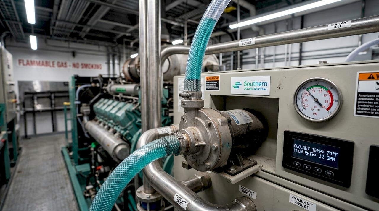
Liquid cooling is the dominant method for industrial gas generators. A coolant pump circulates a water-glycol mixture through passages machined into the engine block and cylinder head, known as the water jacket. The heated coolant then travels to a heat exchanger or radiator where it releases heat to ambient air before returning to the pump. Remote radiators route heated jacket coolant to outdoor locations where fans transfer heat to air before cooled coolant returns to the engine pump. This closed-loop architecture prevents coolant loss and allows precise temperature regulation.
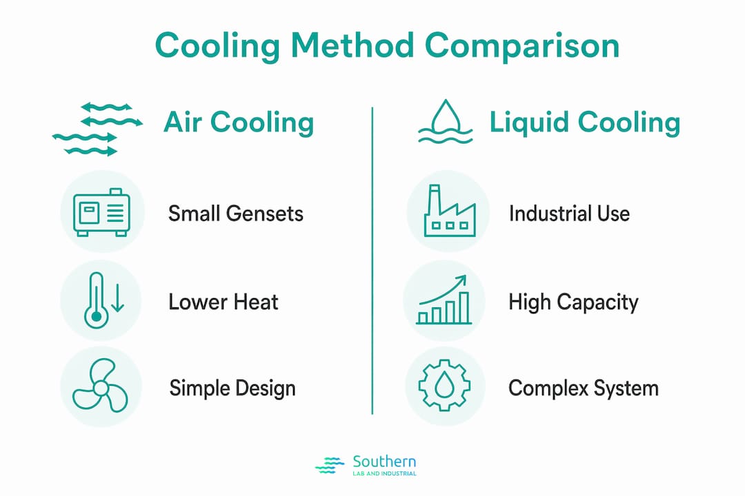
Air cooling applies primarily to smaller, portable gas generators below roughly 20 kW. Fins cast into the cylinder block and head increase surface area, and a shroud-mounted fan forces ambient air across those fins. The simplicity of this approach reduces component count, but heat rejection capacity is limited. Air-cooled designs are not suitable for continuous-duty industrial applications where heat loads are sustained and ambient temperatures are variable.
Hydrogen gas cooling is a specialized technique used in large utility-scale generators, not in the reciprocating gas gensets typical of industrial facilities. In those machines, hydrogen circulates inside the sealed stator housing to remove heat from the windings. The thermal conductivity of hydrogen is roughly seven times that of air, which makes it highly effective at this scale. For the reciprocating gas generators that SLI’s industrial clients operate, liquid cooling with remote radiators is the standard architecture.
Comparison of cooling methods
| Cooling method | Typical application | Heat rejection capacity | Key advantage |
|---|---|---|---|
| Air-cooled | Portable generators under 20 kW | Low | Simple, low maintenance |
| Liquid-cooled, unit-mounted radiator | Mid-range gensets 20 kW to 500 kW | Medium | Compact, self-contained |
| Liquid-cooled, remote radiator | Large industrial gensets 500 kW and above | High | Flexible placement, reduced engine room heat |
| Hydrogen gas-cooled | Utility turbogenerators | Very high | Exceptional thermal conductivity |
What are the key components in a generator cooling system?
The cooling mechanism in gas generators depends on several interdependent components, each with a defined function. A failure in any one of them cascades quickly into overtemperature conditions.
- Coolant pump: Drives flow through the water jacket and external heat exchanger circuit. Flow rate directly determines heat transfer capacity. An undersized or worn pump reduces flow and raises jacket water temperature under load.
- Thermostat and temperature control valves: Regulate coolant temperature by controlling the proportion of flow routed through the radiator versus bypassed directly back to the engine. Wax-element thermostats are common in smaller gensets; larger industrial units use 3-way blending valves with electric actuation for tighter control.
- Radiator or remote heat exchanger: Transfers heat from coolant to ambient air. Fin-and-tube construction maximizes surface area. Fouling of the fin surfaces is the most common cause of reduced heat rejection capacity in field installations.
- Cooling fans: Force air across the radiator core. Axial fans are standard for unit-mounted radiators; variable-speed drives on fan motors optimize thermal control and reduce energy consumption at partial load.
- Expansion tank: Accommodates coolant volume changes as temperature rises and falls. It also provides a point for pressure relief and coolant level monitoring.
- Temperature sensors and generator controller: Monitor jacket water outlet temperature, oil temperature, and charge air temperature in real time. Generator control systems include high-temperature shutdown protections that activate automatically if critical temperature thresholds are exceeded.
Pro Tip: When troubleshooting a high-temperature alarm, check the expansion tank cap and pressure relief valve before assuming a pump or thermostat failure. A failed cap that cannot hold system pressure causes coolant to boil at lower temperatures and triggers false overtemperature events.
The interaction between the thermostat and the fan control is worth understanding in detail. At low ambient temperatures or light loads, the thermostat restricts flow to the radiator to prevent overcooling. Simultaneously, the fan may run at reduced speed or cycle off. As load increases, the thermostat opens progressively, and fan speed ramps up. This coordinated response keeps jacket water temperature stable across a wide operating range.
How do multi-loop cooling circuits improve performance?
Industrial gas generators, particularly large natural gas gensets from manufacturers like Jenbacher, use separate cooling circuits for jacket water, lubrication oil, and charge air. Each circuit has a different target temperature, and each requires its own control strategy.
- Jacket water circuit: Targets approximately 85°C to 95°C. This circuit removes heat from the combustion chamber walls and cylinder head. It carries the largest heat load of the three circuits.
- Lubrication oil cooling circuit: Targets approximately 70°C to 80°C. Oil that runs too hot loses viscosity and accelerates bearing wear. Oil that runs too cold increases viscosity and reduces flow to critical surfaces. A plate-type oil cooler, typically cooled by jacket water, maintains this balance.
- Charge air cooling circuit: Targets approximately 40°C to 55°C depending on engine design. Cooling the intake charge increases its density, which improves combustion efficiency and reduces knock risk. This circuit often uses a separate low-temperature coolant loop or ambient air.
3-way temperature control valves blend hot and cold coolant flows, with electric actuation providing tight, adjustable temperature regulation. Electric actuators respond faster than wax-element valves and can be integrated with the engine management system for load-dependent setpoint adjustment. This matters during rapid load changes, when heat rejection demand can shift significantly within seconds.
Multi-loop temperature control valves improve system stability by preventing overcooling and overheating during load and ambient temperature swings. The practical implication is that a genset with electric-actuated 3-way valves on all three circuits will hold tighter temperature tolerances than one relying on wax thermostats alone, which translates directly to longer component life and fewer unplanned shutdowns.
Pro Tip: In multi-loop systems, faults in one circuit can mask or mimic faults in another. If jacket water temperature rises unexpectedly, verify that the charge air cooler circuit is not restricting flow before condemning the jacket water thermostat. Coupled control loops require systematic diagnostics, not single-component assumptions.
The diagnostic complexity of multi-loop systems is real. Multiple coupled control loops require coordinated monitoring because faults in one loop can cause thermal instability in others. Investing in a generator controller with loop-specific temperature trending and alarm differentiation pays for itself quickly in reduced diagnostic time.
What does cooling system sizing and maintenance require?
Gas generator heat management starts at the design stage. Cooling system design must match heat rejection capacity to engine load and ambient conditions, because undersizing leads to overheating and reduced genset life. For a 1,550 kW gas genset, heat rejection via remote radiators reaches 1.4 to 1.8 MW. That figure illustrates why radiator selection cannot be based on nameplate generator output alone. You must account for the full heat balance, including jacket water, oil cooler, and charge air contributions.
Ambient temperature and installation altitude both reduce cooling capacity. At higher altitudes, air density drops, which reduces the heat transfer coefficient of the radiator. At elevated ambient temperatures, the temperature differential between coolant and air shrinks, which reduces heat rejection rate. Both effects require derating the radiator capacity or increasing fan airflow.
Key maintenance tasks for cooling system reliability
- Radiator fin cleaning: Fouled fins are the leading cause of reduced heat rejection in field installations. Clean with low-pressure compressed air or water from the air-exit side to push debris back out the air-entry side. Frequency depends on environment; dusty or oily atmospheres may require monthly cleaning.
- Coolant level and quality checks: Verify coolant level in the expansion tank at every scheduled service. Test glycol concentration and inhibitor levels at least annually. Degraded inhibitors allow corrosion inside the water jacket and heat exchanger, which reduces flow area over time.
- Thermostat and valve function tests: A thermostat stuck open causes chronic overcooling and increased fuel consumption. A thermostat stuck closed causes rapid overtemperature. Bench-test thermostats annually or replace on a fixed interval.
- Fan belt and bearing inspection: Belt-driven fans lose tension over time. A slipping belt reduces airflow and raises coolant temperature under load. Check tension and condition at every oil change interval.
- Ventilation path verification: Generator manuals emphasize the critical need for unobstructed ventilation airflow to prevent overheating-related damage. Verify that no equipment, stored materials, or structural modifications have reduced the effective inlet or outlet area since the last inspection.
Cooling system sizing reference
| Parameter | Design input | Impact if undersized |
|---|---|---|
| Heat rejection load (kW) | Engine heat balance data | Chronic overtemperature |
| Ambient temperature (°C) | Site weather data, worst case | Reduced temperature differential |
| Altitude (m above sea level) | Site survey | Reduced air density, lower fan performance |
| Airflow (m³/h) | Fan selection and duct sizing | Insufficient heat transfer at radiator |
Remote radiator placement improves airflow management and reduces heat load within engine rooms, enhancing reliability beyond just temperature control. For industrial facilities where engine room temperatures are already elevated by other equipment, this benefit is substantial. Multi-fan remote radiator designs provide redundancy and can be staged with variable speed drives to match cooling demand efficiently, which also reduces fan motor energy consumption during partial-load operation.
Key takeaways
Gas generator cooling systems require correctly sized, properly maintained multi-loop circuits to protect engine components and sustain reliable output across varying load and ambient conditions.
| Point | Details |
|---|---|
| Cooling circuit architecture | Industrial gas gensets use separate jacket water, oil, and charge air loops, each with distinct temperature targets. |
| Remote radiator advantage | Relocating heat exchangers outside the engine room reduces ambient heat buildup and simplifies maintenance access. |
| Electric valve actuation | Electric 3-way blending valves hold tighter temperature tolerances than wax thermostats during rapid load changes. |
| Maintenance priority | Cleaning radiator fins and verifying unobstructed ventilation paths prevents the majority of field overtemperature events. |
| Sizing discipline | Heat rejection capacity must account for full engine heat balance, ambient temperature, and altitude, not generator nameplate output alone. |
Why cooling system design deserves more engineering attention than it gets
From my experience working with industrial gas generator installations, cooling systems are consistently underspecified at the procurement stage and underserviced in the field. Engineers spend significant time on fuel system design, electrical protection, and control integration, but cooling often gets treated as a catalog selection rather than an engineered subsystem.
The multi-loop control interaction issue is where I see the most diagnostic errors. A technician sees a jacket water high-temperature alarm and immediately suspects the thermostat or pump. In reality, a fouled charge air cooler or a partially closed valve in the oil circuit can shift heat loads in ways that stress the jacket water circuit indirectly. You cannot diagnose these systems in isolation. You need trending data from all three loops simultaneously, and you need a controller that logs each loop independently.
Remote radiator systems are underutilized in Gulf Coast industrial facilities, where ambient temperatures and engine room heat loads are both high. Moving the heat exchanger outside the building solves two problems at once: it removes heat from the engine room, which protects other equipment, and it gives the radiator access to ambient air that has not already been warmed by the generator itself. The energy savings from variable-speed fan drives on those remote radiators are a secondary benefit that often justifies the additional capital cost within the first two years of operation.
My practical advice: treat the cooling system as a first-class engineered subsystem. Size it with a margin, specify electric-actuated valves on large gensets, and build a preventive maintenance schedule that prioritizes fin cleaning and ventilation verification above almost everything else. The generators that run for 20 years without major thermal failures are the ones where someone made those decisions deliberately at the start.
— Kris
How SLI supports industrial gas generator reliability

SLI works with engineers and facility managers across the Gulf Coast who need gas generation systems that perform reliably under demanding industrial conditions. Whether you are evaluating on-site hydrogen and nitrogen generators for analytical or process applications or need technical guidance on cooling system design for your facility, SLI brings hands-on expertise from installation through long-term maintenance. SLI partners with LNI Swissgas and Nel Hydrogen to provide certified equipment backed by local technical support. For engineers focused on flow rate and thermal performance, the gas generator flow rate guide covers the engineering fundamentals that connect cooling capacity to generator output and system design.
FAQ
How does a gas generator cooling system work?
A gas generator cooling system circulates coolant through the engine water jacket to absorb combustion heat, then routes that heated coolant to a radiator or remote heat exchanger where fans transfer the heat to ambient air before the cooled coolant returns to the engine.
What is the difference between air-cooled and liquid-cooled gas generators?
Air-cooled generators use fins and a fan to dissipate heat directly from the engine block, making them suitable for small portable units. Liquid-cooled generators circulate a water-glycol mixture through internal passages and external heat exchangers, providing far greater heat rejection capacity for continuous industrial operation.
Why do large industrial gas gensets use remote radiators?
Remote radiators relocate the heat exchanger outside the engine room, which prevents recirculation of hot exhaust air back into the cooling system and reduces the ambient temperature around other equipment. A 1,550 kW gas genset can reject 1.4 to 1.8 MW of heat, a load that unit-mounted radiators cannot manage effectively in confined spaces.
What causes most overtemperature shutdowns in gas generators?
Fouled radiator fins and obstructed ventilation paths are the most common causes of overtemperature shutdowns in field installations. Both conditions reduce heat rejection capacity without triggering any alarm until the jacket water temperature exceeds the shutdown threshold.
How often should gas generator cooling systems be serviced?
Coolant level and quality should be checked at every scheduled service interval, with inhibitor testing at least annually. Radiator fin cleaning frequency depends on the installation environment, but dusty or oily conditions may require monthly inspection and cleaning to maintain rated heat rejection capacity.