Gas generator piping installation is the process of designing and physically constructing the fuel supply system that delivers natural gas or propane at the correct pressure and flow rate to a generator engine. A failed piping installation does not just cause startup problems. It causes load shedding, regulator damage, and unplanned downtime that costs far more than the installation itself. This guide covers every phase of the process, from material selection and code compliance through regulator placement, physical routing, and commissioning, with the specificity that working technicians and engineers actually need.
Gas generator piping installation guide: tools, materials, and prerequisites
Before any pipe is cut or fitting threaded, the site must be prepared and all materials verified against applicable codes. NFPA 37 governs stationary combustion engines, NFPA 54 covers natural gas fuel gas codes, and NFPA 58 applies to liquefied petroleum gas systems. Permits are required in virtually every jurisdiction, and inspections are typically required before the system is placed in service. Skipping the permit stage is not a time saver. It creates liability and can void equipment warranties.
Standard tools required
- Pipe cutters and threading dies (for steel pipe) or tube cutters (for copper or CSST)
- Calibrated pressure gauges (0 to 30 in. w.c. and 0 to 15 psig ranges)
- Torque wrenches and pipe wrenches
- Manometer or digital pressure logger for drop testing
- Soap solution or electronic leak detector for post-installation testing
- Pipe supports, clamps, and anchoring hardware
Approved piping materials by code
| Material | Allowed Use | Notes |
|---|---|---|
| Schedule 40 black steel | Natural gas, propane vapor | Most common for commercial/industrial |
| CSST (corrugated stainless steel tubing) | Natural gas, propane vapor | Requires bonding per local code |
| Copper (Type K or L) | Natural gas only (no propane) | Not allowed where propane contacts copper alloys |
| Stainless steel flex connectors | Generator inlet connection | Required for vibration isolation |
Site preparation includes confirming the utility meter capacity, verifying available inlet pressure, and establishing a clear pipe route that minimizes total run length and number of fittings. Confirm the generator manufacturer’s minimum inlet pressure specification before sizing begins. Most generator engines require 11 or 14 inches water column at the fuel inlet depending on model, and the entire piping system must be sized to deliver that pressure under full-load conditions.
How to size gas piping and place regulators for stable pressure
Pipe sizing is the single most consequential decision in the entire installation. Undersized gas piping causes pressure droop under load, which triggers low-fuel shutdowns and can permanently damage the engine’s fuel management system. A 500 kW generator supplied through 1.5-inch pipe over a 100-foot run will experience pressure drops that require upsizing to 2-inch pipe. That is not a marginal difference. It is the difference between a generator that runs and one that shuts down under load.
Sizing calculations must account for three variables: total BTU demand at full load, total equivalent pipe length (including fittings converted to equivalent feet), and the allowable pressure drop. Pressure drop must not exceed 2 inches water column from no-load to full-load conditions. For gas generator flow rate calculations, use the generator’s rated BTU/hr input from the nameplate, not the electrical output rating.
Natural gas vs. propane regulator systems
| Parameter | Natural Gas | Two-Stage Propane (NFPA 58) |
|---|---|---|
| First-stage pressure | Utility-supplied (varies) | ~10 psig |
| Second-stage pressure | Single regulator to ~7 in. w.c. | ~10 to 12 in. w.c. |
| Regulator count | One (typically) | Two (first and second stage) |
| Startup starvation risk | Lower | Higher without adequate response volume |
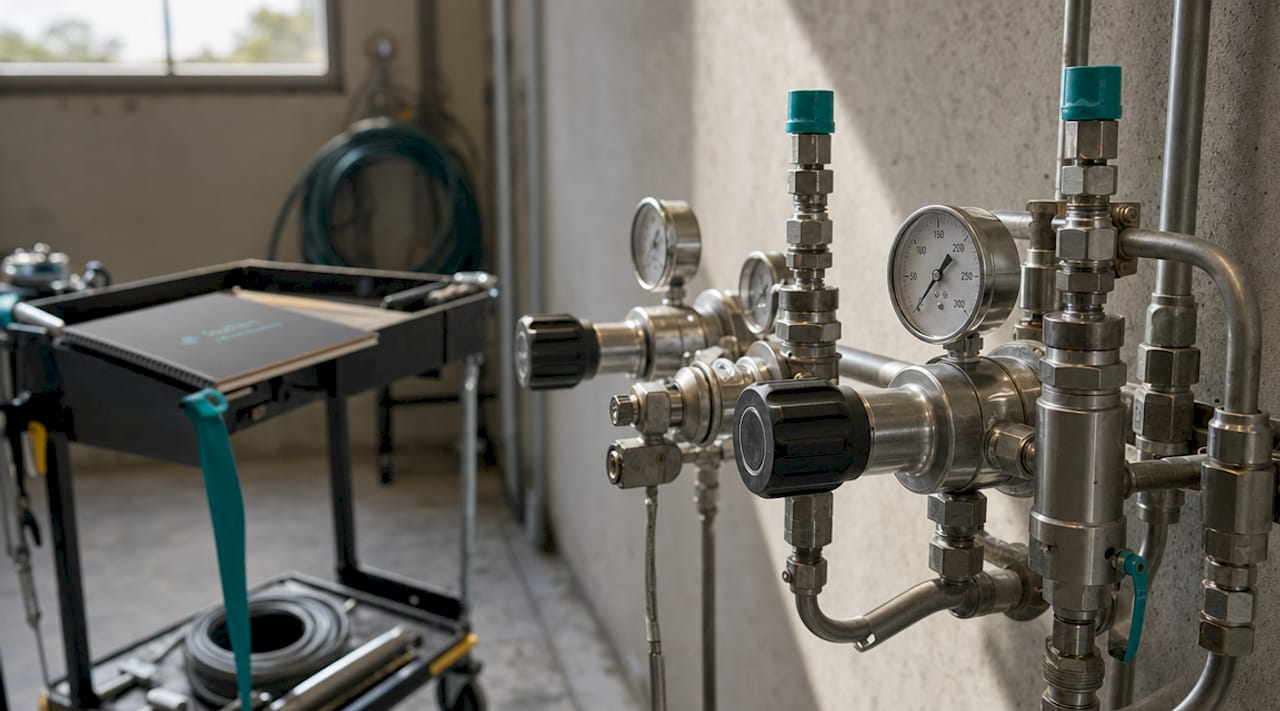
For propane systems, two-stage regulator sizing follows NFPA 58 and NFPA 54, with first-stage piping at 10 psig and second-stage piping at approximately 10 to 12 in. w.c. The distance between the second-stage regulator and the generator inlet matters more than most installers realize. Placing the regulator too close to the generator reduces the volume of gas available during the brief but intense startup demand surge, causing fuel starvation symptoms that look identical to an undersized regulator.
Increasing regulator response volume by upsizing the pipe diameter between the second-stage regulator and the generator, or by relocating the regulator farther from the generator, resolves startup starvation in propane systems. The recommended regulator placement is 8 to 10 feet from the generator inlet. Proper regulator straight-run requirements call for 10 pipe diameters of straight pipe upstream and 5 pipe diameters downstream to maintain laminar flow and accurate pressure sensing.
Pro Tip: Never install a regulator immediately downstream of an elbow or tee. Turbulent flow at the regulator inlet causes pressure sensing errors that no amount of setpoint adjustment will correct.
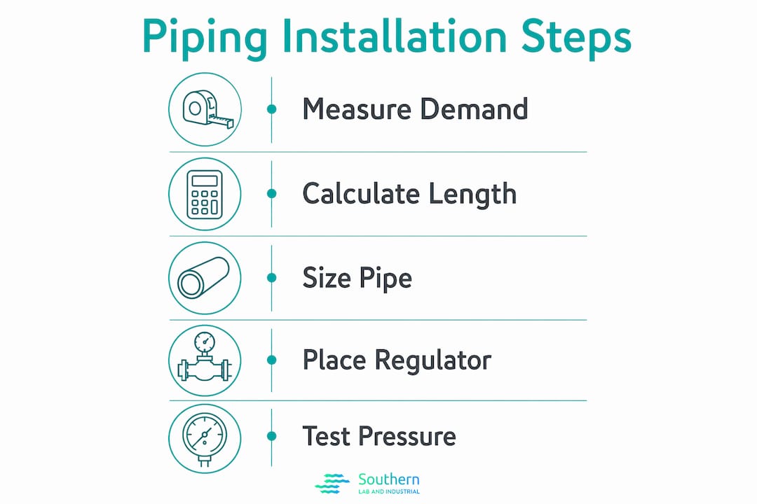
Step-by-step piping installation process
With sizing confirmed and materials on site, the physical installation follows a defined sequence. Deviating from this sequence, particularly by skipping contamination control steps, is the most common cause of commissioning failures.
Lay out the pipe route before cutting any material. Mark support locations every 8 to 10 feet for horizontal runs of 1-inch and larger pipe, and every 6 feet for smaller diameters. Minimize bends. Every 90-degree elbow adds equivalent pipe length and pressure drop.
Install the main shutoff valve at the utility connection point, accessible and clearly labeled. Install a second shutoff valve within 6 feet of the generator for local isolation.
Install drip legs (sediment traps) at all low points in the system and immediately upstream of each regulator. A drip leg is a vertical pipe nipple capped at the bottom, sized to collect condensate and debris before it reaches the regulator seat.
Thread or weld all rigid pipe sections and pressure-test each segment before closing walls or burying runs. Use only listed pipe dope or PTFE tape rated for gas service on threaded connections.
Install flexible stainless steel connectors at the generator inlet. Flexible fuel lines isolate vibration and thermal movement from the rigid piping system, preventing fatigue cracks at fittings over time.
Pig all new gas lines before connecting to the generator or regulators. Pipe pigging clears mill scale, thread shavings, and debris that accumulate during fabrication. Skipping pipe pigging has cost facilities three days of commissioning delay due to regulator seat blockage from debris that entered the fuel train.
Install the regulator assembly with the required straight-run pipe sections upstream and downstream. Confirm the vent is directed away from ignition sources and is not subject to blockage.
Conduct a full pressure test at 1.5 times the maximum operating pressure, held for a minimum of 15 minutes with no measurable drop. Document the test with a calibrated gauge and time-stamped record.
Pro Tip: Install a pressure gauge port immediately upstream and downstream of each regulator during initial installation. These ports cost almost nothing to add during construction and save hours of diagnostic time during commissioning and future troubleshooting.
Pipe support and vibration control
Excessive elbows and missing supports are among the most frequently cited causes of long-term gas delivery problems in generator installations. Supports prevent pipe sag that creates low-point condensate traps and stress concentrations at fittings. Use pipe clamps with rubber-lined saddles on vibration-sensitive runs near the generator. Anchor all vertical risers at the top and bottom. Never allow the generator itself to bear the weight of the connected piping.
Commissioning, testing, and troubleshooting common pitfalls
Commissioning is not a formality. It is the only way to verify that the installed system performs under the actual operating conditions the generator will face. A system that holds pressure at static test can still fail under dynamic load.
The commissioning sequence for a gas generator fuel system includes:
- Static pressure verification: Confirm regulator outlet pressure matches the manufacturer’s setpoint with no load on the generator.
- No-load to full-load pressure drop test: Start the generator and bring it to full rated load using a load bank. Monitor pressure at the regulator outlet and at the generator inlet simultaneously. Pressure drop under full load must stay within 2 in. w.c. of the no-load reading.
- Leak test under operating pressure: Apply soap solution or use an electronic detector at every joint, fitting, and valve body with the system pressurized and the generator running.
- Regulator lockup test: Shut the generator down and confirm the regulator closes completely with no pressure creep on the downstream gauge.
The most common commissioning failure is a pressure drop that only appears at 75 to 100 percent load. This almost always indicates undersized piping, excessive fittings, or a regulator placed too close to the generator. Fuel train commissioning must simulate full-load conditions to catch these faults before the generator enters service. Load bank testing is not optional for critical standby applications.
Troubleshooting fuel starvation symptoms, where the generator starts but shuts down under load, requires checking the pressure at the generator inlet under load, not at the regulator outlet. A large pressure differential between those two points identifies the problem segment precisely.
Key takeaways
Correct gas generator piping requires accurate pipe sizing, regulator placement at 8 to 10 feet from the generator inlet, drip leg installation, pipe pigging before commissioning, and full-load pressure drop verification within 2 in. w.c.
| Point | Details |
|---|---|
| Pipe sizing drives reliability | Undersized pipe causes pressure droop under load; size for full BTU demand plus fitting losses. |
| Regulator placement is critical | Place the second-stage regulator 8 to 10 feet from the generator inlet to prevent startup fuel starvation. |
| Straight runs protect regulator accuracy | Install 10 pipe diameters upstream and 5 downstream of every regulator to maintain laminar flow. |
| Pig lines before commissioning | Debris from new pipe construction blocks regulator seats and can delay commissioning by days. |
| Full-load testing is mandatory | Static pressure tests do not reveal dynamic pressure drops; always test at 100 percent rated load. |
What field experience actually teaches about gas piping installations
I have reviewed enough generator commissioning reports to say with confidence that the majority of post-installation failures trace back to decisions made during design, not during construction. The pipe was installed correctly. The fittings were tight. The regulator was set to spec. But the pipe was sized for the generator’s electrical output instead of its BTU input, or the regulator was placed 18 inches from the generator because the mechanical room was tight, or nobody pigged the lines because the schedule was compressed.
The detail that surprises most engineers the first time they encounter it is the regulator response volume issue in propane systems. You can install a regulator that is rated for twice the generator’s demand, set it perfectly, and still get fuel starvation on startup because there is not enough gas volume between the regulator and the engine to satisfy the initial demand surge before the regulator has time to respond. Upsizing the regulator does nothing. Moving it farther away, or upsizing the connecting pipe, solves the problem immediately.
The other lesson that does not appear in most installation manuals is the value of pressure gauge ports. Adding a 1/4-inch NPT gauge port upstream and downstream of every regulator during initial construction takes ten minutes and costs almost nothing. During commissioning and every troubleshooting call afterward, those ports tell you exactly where the pressure is dropping. Without them, you are guessing. With them, you have a diagnostic tool built into the system permanently.
For facilities on the Gulf Coast managing gas generator integration challenges in industrial environments, the commissioning rigor described here is not excessive. It is the minimum standard for a system that needs to start reliably under emergency conditions.
— Kris
Professional support for gas generator piping and integration
SLI provides engineering support and turnkey installation services for gas generator fuel systems in industrial facilities and analytical laboratories along the Gulf Coast.

Whether you are sizing a new natural gas supply for a standby generator or troubleshooting an existing propane system with startup starvation symptoms, SLI’s technical team works through the full installation process, from BTU load calculations and pipe sizing through regulator selection, commissioning, and load bank testing. For facilities dealing with complex generator integration challenges, SLI offers site assessments and detailed engineering reviews that identify code compliance gaps and performance risks before they become operational problems. Contact SLI at getsli.com to discuss your specific installation requirements.
FAQ
What is the maximum allowable pressure drop in gas generator piping?
Pressure drop must not exceed 2 inches water column from no-load to full-load conditions at the generator fuel inlet. Exceeding this threshold causes performance degradation and potential shutdown under load.
How far should the regulator be from the generator inlet?
The recommended placement is 8 to 10 feet from the generator inlet. Closer placement reduces the gas volume available during startup demand surges, causing fuel starvation symptoms in both natural gas and propane systems.
Why is pipe pigging required before commissioning?
New gas lines contain mill scale, thread shavings, and construction debris that block regulator seats and damage fuel train components. Pipe pigging before commissioning prevents regulator damage and costly disassembly during startup.
What straight-run pipe length is required at a gas regulator?
Regulators require 10 pipe diameters of straight pipe upstream and 5 pipe diameters downstream. This maintains laminar flow at the sensing port and prevents pressure instability caused by turbulence.
What causes fuel starvation symptoms in propane generator systems?
Fuel starvation on startup is most often caused by insufficient regulator response volume, not an undersized regulator. Relocating the second-stage regulator farther from the generator or upsizing the connecting pipe resolves the issue by increasing available gas volume during the initial demand surge.